Power capacitor with improved internal fuse structure

A technology of power capacitors and internal fuses, applied in the direction of capacitors, electrical components, etc., can solve problems such as affecting the electrical performance of capacitors, and achieve the effect of avoiding electrical performance and avoiding diffusion

Inactive Publication Date: 2015-01-28
CHINT ELECTRIC
View PDF7 Cites 1 Cited by
  • Summary
  • Abstract
  • Description
  • Claims
  • Application Information

AI Technical Summary

Problems solved by technology

[0004] The purpose of the present invention is to provide a new assembly structure of the fuse in the power capacitor and its manufacturing method to solve the problem that the improper placement of the fuse affects the compression coefficient of the component and thus affects the electrical performance of the capacitor

Method used


Image

  • Power capacitor with improved internal fuse structure
  • Power capacitor with improved internal fuse structure
  • Power capacitor with improved internal fuse structure

Examples


Embodiment

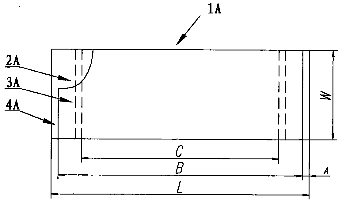
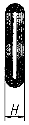
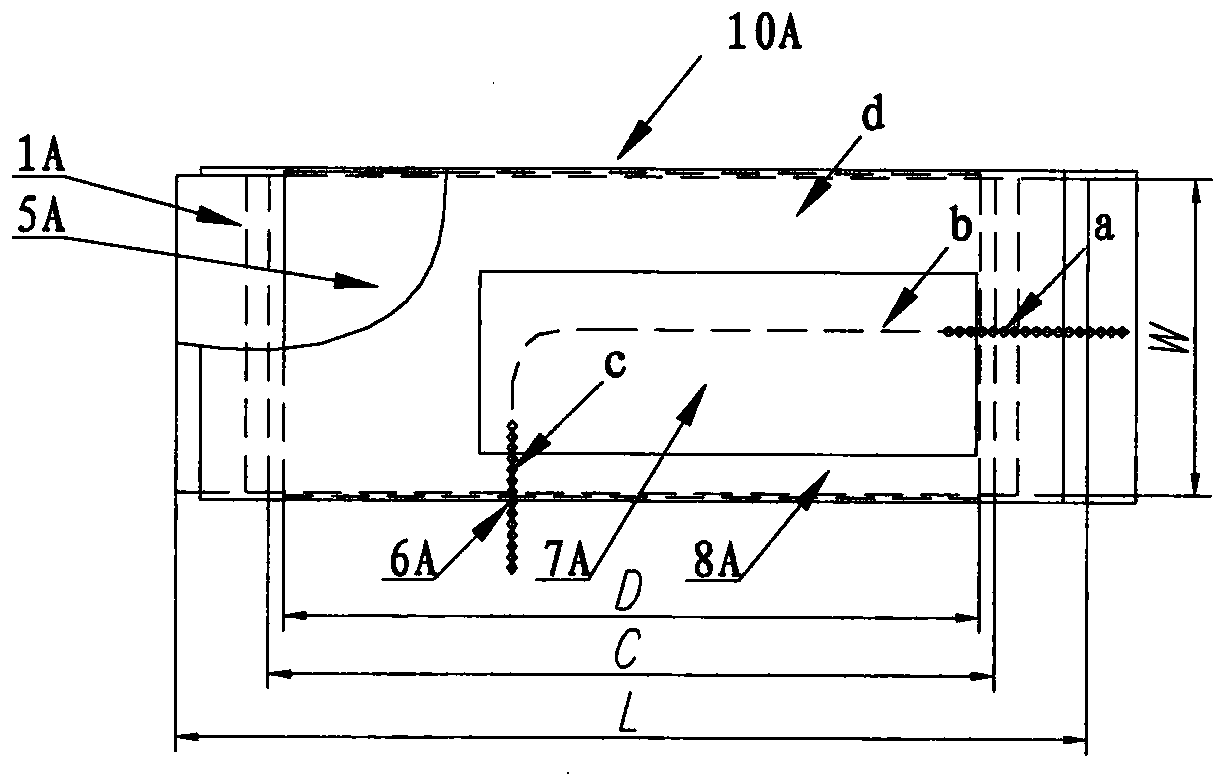
[0044] Such as Figure 14 and 15 As shown, the power capacitor with an improved internal fuse structure of the present invention includes a core 20 disposed in the capacitor casing, and the core 20 includes a plurality of welded assemblies 23, 24, 25. Each welding assembly 23, 24, 25 includes a plurality of capacitive element assemblies 10, such as Figure 11 As shown, each capacitive element assembly 10 includes a capacitive element 1, an element inner liner 5A, an element outer liner 8A, a fuse 6A and an adhesive tape 7, wherein the structure of the capacitive element 1 is as follows Figure 13 shown. The element inner liner 5A is arranged on the outside of the capacitor element 1, and the element outer liner 8A is arranged on the outside of the element inner liner 5A. The fuse 6A includes a melt part and terminals arranged at both ends of the melt part. The melt part of the fuse 6A is fixed on the non-stacked side of the element inner liner 5A by adhesive tape 7 and is l...


PUM


Abstract

The invention provides a power capacitor with an improved internal fuse structure. The power capacitor comprises a core arranged in a capacitor housing, wherein the core comprises a plurality of mutually stacked welding components; each welding component comprises a plurality of capacitive element assemblies; each capacitive element assembly comprises a capacitive element, an element inside liner, an element outside liner, a fuse and an adhesive tape; and each fuse comprises a fusant part and terminals arranged at the two ends of the fusant part. The power capacitor is characterized in that the fusant parts of the fuses are fixed on non-stacking sides of the element inside liners by the adhesive tapes, and located between the element inside liners and the element outside liners; one terminal of each fuse is electrically connected with an electrode of each capacitive element; and the other terminal of each fuse extends out of a hole of each element outside liner. The power capacitor does not influence a compaction factor of an element, and an influence on the electric performance of the capacitor can be further avoided.

Description

technical field [0001] The invention belongs to the field of power capacitor manufacturing, and relates to a power capacitor and a manufacturing method thereof, in particular to the overall structure of its internal fuse and a new scheme for electrical connection processing. Background technique [0002] In the field of power capacitor manufacturing, internal fuses are widely used in high-voltage parallel and high-voltage series capacitors. The components and the circuit are effectively disconnected. Since the capacitance value does not change much, the capacitor can still continue to operate, which avoids the early damage of individual components causing the entire capacitor to quit operation, thereby prolonging the service life of the capacitor and reducing the damage rate during operation. Improve operational reliability. Figure 1 to Figure 10 The basic assembly configuration of existing capacitors with internal fuses is given, see figure 1 and figure 2 , each capaci...

Claims


Application Information

Patent Timeline
IPC IPC(8): H01G2/16
Inventor 张雅舒王宁来周存和李新民
Owner CHINT ELECTRIC
Why Eureka
Try Eureka