High-speed on demand droplet generation and single cell encapsulation driven by induced cavitation

A droplet and cavitation bubble technology, applied in the field of microfluidics, can solve the problems of slow droplet generation, increased design equipment complexity, and incorporation

Active Publication Date: 2015-01-28
RGT UNIV OF CALIFORNIA
View PDF11 Cites 5 Cited by
  • Summary
  • Abstract
  • Description
  • Claims
  • Application Information

AI Technical Summary

Problems solved by technology

However, the droplet generation of this method is relatively slow, producing only about 15-25 droplets per second per nozzle
Although these methods avoid the use of mechanical components, they require the incorporation of electrodes, resistive heaters, or similar components into the device
This increases the complexity of designing the device and further requires the use of support features to reliably supply current

Method used


Image

  • High-speed on demand droplet generation and single cell encapsulation driven by induced cavitation
  • High-speed on demand droplet generation and single cell encapsulation driven by induced cavitation
  • High-speed on demand droplet generation and single cell encapsulation driven by induced cavitation

Examples


Embodiment 1

[0086] Droplet generation driven by pulsed laser-induced cavitation

[0087] Constructed using standard soft lithography techniques image 3 The pulsed laser-driven droplet generation (PLDG) device shown. The PLDG device has two fluid channels, one filled with water and the other filled with oil. Both fluidic channels are 100 microns wide and 100 microns high. The fluid channels are connected by an opening configured as a nozzle, the neck of which is 30 microns wide. Adjust the flow rate in the channel to create a stable oil / water interface.

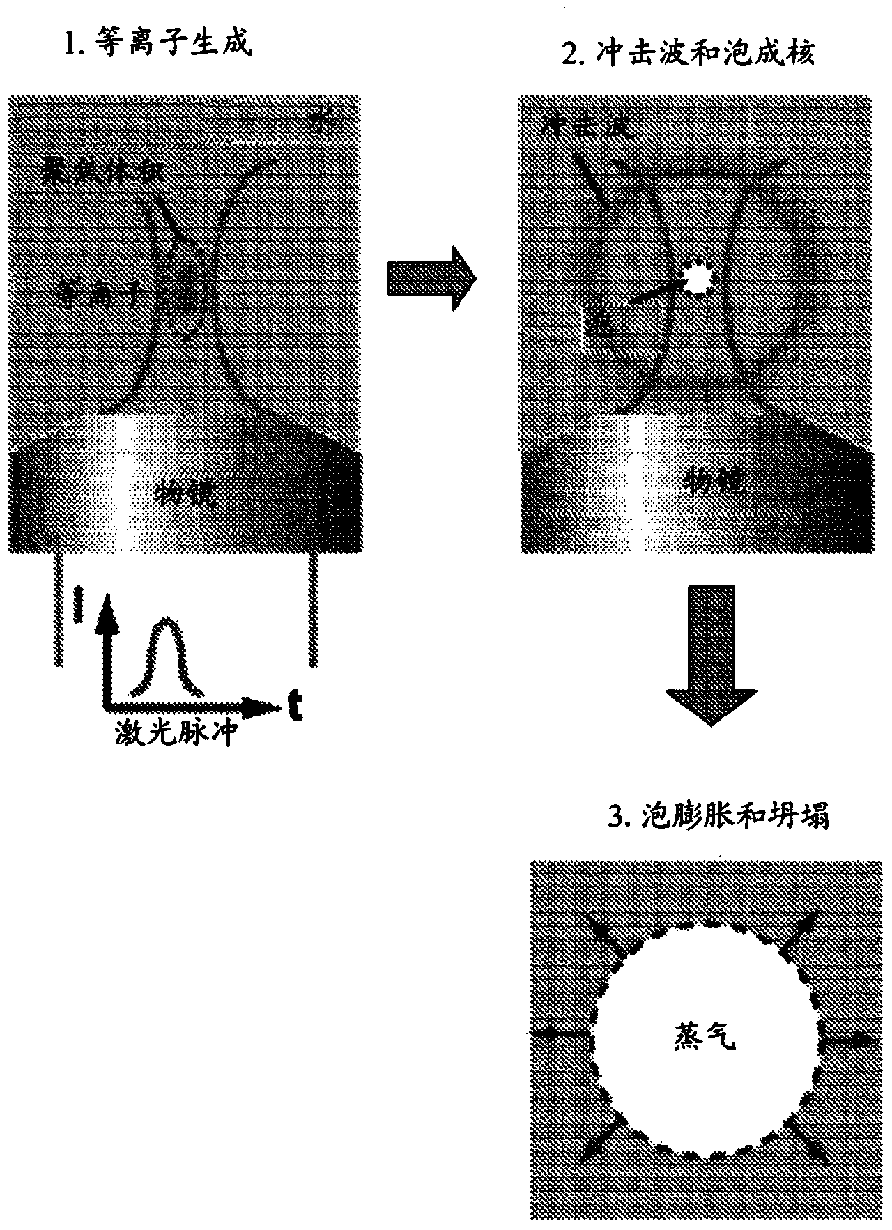
[0088] The PLDG device is actuated based on cavitation bubbles induced by laser pulses, which are generated when intense laser pulses are focused on the fluid channels containing them. Plasma formation at the focal point of the laser pulse can generate rapidly expanding cavitation bubbles, as described above. This disturbs the oil / water interface and pushes water droplets into adjacent oil-filled fluid channels to form stable wate...

Embodiment 2

[0091] Volume control of PLDG-generated droplets

[0092] The volume of PLDG can be controlled by adjusting the energy delivered by the pulsed laser as a function of laser intensity and pulse duration, location of laser excitation, or a combination thereof. Alternatively, the energy of the pulsed laser can be adjusted using a beam deflector.

[0093] Figure 9 The figure shows that the volume of droplets produced by PLDG can be controlled by adjusting these parameters. Droplets are made of Figure 9 Panels (a) to (d) show the effect of varying the laser energy at a fixed distance of 47 microns from the nozzle ( Figure 9 Among them, panel (a)=100 μJ, panel (b)=90 μJ, panel (c)=80 μJ, panel (d)=70 μJ). This produces a controlled droplet size ranging from about 55 to about 5 microns, which decreases with decreasing laser energy.

[0094] The control droplet size is shown in Figure 9 Panels (e) to (g) where the laser energy was kept constant at 100 microjoules and the di...

Embodiment 3

[0096] The consistency of the size of the droplets produced by PLDG (Consistency)

[0097] Because PLDG is an on-demand method, PLDG is able to generate droplets at different frequencies by controlling the interval between laser pulses. Figure 10 shown in 2 milliseconds ( Figure 10 panel (a)) to 100 microseconds ( Figure 10 Panel (d)) Results of continuous droplet generation for different firing intervals. The flow rate of the fluid channel receiving the droplets is adjusted to maintain the dispersion of the droplets at a high droplet generation rate.

[0098] Figure 11 Schematic liquids collected at droplet generation frequencies of 1 kHz (panel (a)) and 10 kHz (panel (b)) are shown. The droplet size is consistent despite a 10-fold difference in the velocity at which the droplets are formed. Figure 12 Results of similar studies are shown, with the intervals between laser excitations set at 2 milliseconds (panel (a)), 500 microseconds (panel (b)) and 100 microsecon...


PUM


Abstract

Methods and devices for the formation of droplets of a first fluid in a second fluid and the encapsulation of particles or cells within such droplets are disclosed. Impetus for droplet formation is provided by the creation of a transient bubble, which may be induced using a pulsed laser. Droplet volume and the frequency at which droplets are formed can be controlled by modulation of the pulsed laser. The disclosed methods and devices are particularly suitable for use in microfluidic devices.

Description

[0001] Cross References to Related Applications [0002] This application claims the benefit of and priority to USSN 13 / 370,196, filed February 9, 2012, which is hereby incorporated by reference in its entirety for all purposes. [0003] Statement of Government Support [0004] This invention was made with government support under Grant Nos. NCC2-1364 to NASA, Grant No. Y018228 to the National Institutes of Health; and Grant Nos. 0747950, 0852701, and 0901154 to the National Science Foundation. The government has certain rights in the invention. technical field [0005] The present invention relates to the field of microfluidics. In certain embodiments, methods and apparatus for forming droplets and / or encapsulating droplets, particles, and / or cells at high speed are provided. Background technique [0006] Microfluidic devices have attracted a lot of attention because they provide platforms for performing analyzes on extremely small volumes of fluids and, when photolithog...

Claims


Application Information

Patent Timeline
Patent Type & Authority Applications(China)
IPC IPC(8): G01N35/08G01N15/14G01N1/28
CPCB01J13/04G01N2015/1481G05D11/13G01N21/64G01N15/10G01N29/2418G01N2291/02433B01L3/502761B01L3/502784B01L2200/0636B01L2200/0668B01L2200/0673B01L2300/0816B01L2400/0442Y10T137/0318Y10T137/2496B01J4/008B01J19/121B01J2219/00164B01J2219/0869B01J2219/12B01L3/502715B01L2200/0647B01L2400/0403
Inventor 邱培钰吴婷翔朴成用迈克尔·A·泰特尔
Owner RGT UNIV OF CALIFORNIA
Why Eureka
Try Eureka