
a spinal fixator

A fixator and spine technology, applied in the direction of fixators, external fixators, internal fixators, etc., can solve the problems of large trauma for bracket installation and complicated fixation surgery, and achieve the advantages of reducing the degree of trauma, simple installation and operation, and high convenience Effect

Inactive Publication Date: 2017-01-18
THE FIRST PEOPLES HOSPITAL OF NANTONG
View PDF2 Cites 5 Cited by
  • Summary
  • Abstract
  • Description
  • Claims
  • Application Information

AI Technical Summary

Problems solved by technology

[0006] The technical problem to be solved by the present invention is to overcome the technical problems of large trauma and complicated fixation surgery in the prior art, and provide an orthopedic fixation bracket with less trauma to the installer, which can reduce or even require secondary surgery

Method used


Image

  • a spinal fixator
  • a spinal fixator
  • a spinal fixator

Examples


Embodiment 1

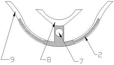
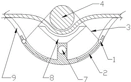
[0039] Specific as figure 1 , figure 2 , image 3 with Figure 5 As shown, this product mainly includes a fixed section and a connecting rod 7 used to connect each fixed section. The connecting rod 7 is made of aluminum alloy and is manufactured according to the patient's specific spine shape.

[0040] The fixed section includes an external spine top frame, an internal vertebral surface fixator and a support 9. The support is an arc-shaped deployment surface that contacts both sides of the human spine and provides support for fixing cables. A number of hollow grooves perpendicular to the longitudinal axis of the unfolding surface are provided on the unfolding surface. A fixing rod 2 is arranged in the hollow groove, and a fixing block 1 is arranged on both sides of the fixing rod 2, and a fixing block 1 is arranged between the fixing blocks 1. There are fixed cables 3;

[0041] The support 9 is provided with a vertical column in the middle, and the external vertebral top frame 8 ...

Embodiment 2

[0049] Such as Figure 4 As shown, the present invention can also be used to fix arms and legs in an emergency state;

[0050] Mainly specific as figure 1 , figure 2 , image 3 with Figure 5 As shown, this product mainly includes a fixed section and a connecting rod 7 used to connect each fixed section. The connecting rod 7 is made of aluminum alloy and is manufactured according to the patient's specific spine shape.

[0051] The fixed section includes an external spine top frame, an internal vertebral surface fixator and a support 9. The support is an arc-shaped deployment surface that contacts both sides of the human spine and provides support for fixing cables. A number of hollow grooves perpendicular to the longitudinal axis of the unfolding surface are provided on the unfolding surface. A fixing rod 2 is arranged in the hollow groove, and a fixing block 1 is arranged on both sides of the fixing rod 2, and a fixing block 1 is arranged between the fixing blocks 1. There are f...


PUM


Abstract

The invention relates to a vertebra fixator, which comprises a connecting rod and at least two fixing sections, wherein each fixing section comprises an external vertebrate top frame, an external vertebra surface fixator and a supporter, the supporter is an arc-shaped unfolding surface, a plurality of hollow grooves vertical to the longitudinal axial line of the unfolding surface are formed in the unfolding surface of the arc surface, fixing rods are arranged in the hollow grooves, at least one fixing block is respectively arranged at each of two sides of each fixing rod, a fixing cable is arranged between the fixing blocks, an upright post is arranged in the middle part of the supporter, the external vertebrate top frame is arranged on the upright post and comprises an arc-shaped support surface coaxial with the unfolding surface of the supporter, a support framework used for fixing the vertebrate is defined between the arc-shaped support surface and the fixing cables arranged among the fixing joints, an installing hole parallel to the axial line of the arc-shaped support surface is arranged in the upright post of the supporter, and the supporter is connected through a connecting rod arranged in the installing hole.

Description

Technical field [0001] The invention relates to a spinal bone fixator, and relates to an external bone fixator that uses a cable for rib fixation. Background technique [0002] In orthopedic treatments such as fractures, various stents are often used to penetrate the skin after the operation to fix the bones to restore them. After recovery, the stents are removed through trauma surgery. The entire process requires multiple operations. The trauma to human muscles and epidermis is relatively large, and the postoperative recovery period is relatively long. At the same time, traditional stents bring relatively large compression and trauma to the bones; [0003] In this regard, there are many orthopedic fixators available on the market that can reduce the degree of trauma during surgery and the number of operations to a certain extent, and at the same time accelerate healing, such as the invention with patent number ZL201120537796.6, which proposes a The steel wire wrapped in the bones...

Claims


Application Information

Patent Timeline
Patent Type & Authority Patents(China)
IPC IPC(8): A61B17/70
CPCA61B17/66A61B17/7001A61B17/7053A61B17/7074A61B2017/00831A61B2017/564A61B2017/7073
Inventor 徐大伟崔志明
Owner THE FIRST PEOPLES HOSPITAL OF NANTONG
Learn More