Forging mould and forming die of forging mould

A molding die and die technology, applied in forging/pressing/hammer devices, forging/pressing/hammering machinery, manufacturing tools, etc., can solve the problems of low processing efficiency, increased scrap rate of parts and low material utilization, etc. Achieve the effect of speeding up processing efficiency and improving processing accuracy

Inactive Publication Date: 2015-02-04
HENAN PINGGAO ELECTRIC +2
View PDF5 Cites 8 Cited by
  • Summary
  • Abstract
  • Description
  • Claims
  • Application Information

AI Technical Summary

Problems solved by technology

[0002] At present, when machining rotary parts whose shape is thick at both ends and small in the middle, two methods are usually used: mechanical cutting and forging. Among them, the traditional processing method is mostly carried out by mechanical cutting, especially turning. It is carried out in the same way, that is, assemble the two ends of the bar on the chuck and the thimble respectively, and then align the turning tool clamped on the tool seat to the part to be processed in the middle of the bar, and finally after turning on the machine tool, turn the turning tool The knife is fed in the axial direction of the bar to process the bar into the required shape, but the utilization rate of the material in the mechanical cutting process is low, so that the cut chips are mixed with a large amount of cutting fluid and cutting impurities Such sundries cannot be reused, and the internal metal lines of the cut parts are destroyed, so that the mechanical properties of the finished product will be seriously reduced, and in severe cases, it will cause the problem of increased scrap rate of parts; although the forging method will not The internal metal texture of the parts is damaged, but the processing efficiency is low. The specific reason is that no matter whether the film forging is used or the forging is carried out on a flat forging machine, the two ends of the parts are limited by the forging abrasives. It cannot be formed at the same time, that is, after upsetting one end of the part, and then upsetting the other end, this processing method not only has the problem of low processing efficiency, but also when one end of the bar is upset, the outer circumference of the other end The surface and the end surface will be deformed at the same time, so that the reduction of the length of the bar during the upsetting process is uncontrollable, so that there is a large error in the length and dimension of the finished parts, and subsequent mechanical cutting processing is often required to compensate for forging processing The resulting error, so there is still the problem of poor mechanical properties of parts

Method used


Image

  • Forging mould and forming die of forging mould
  • Forging mould and forming die of forging mould
  • Forging mould and forming die of forging mould

Examples


Embodiment Construction

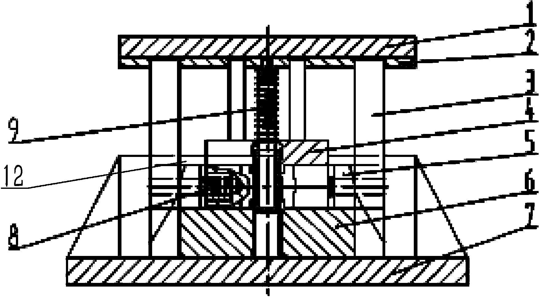
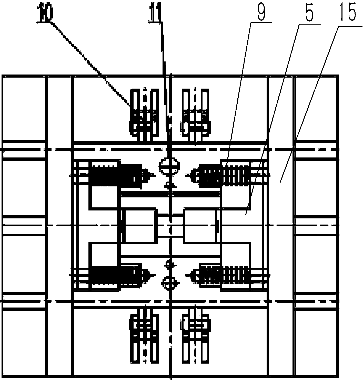
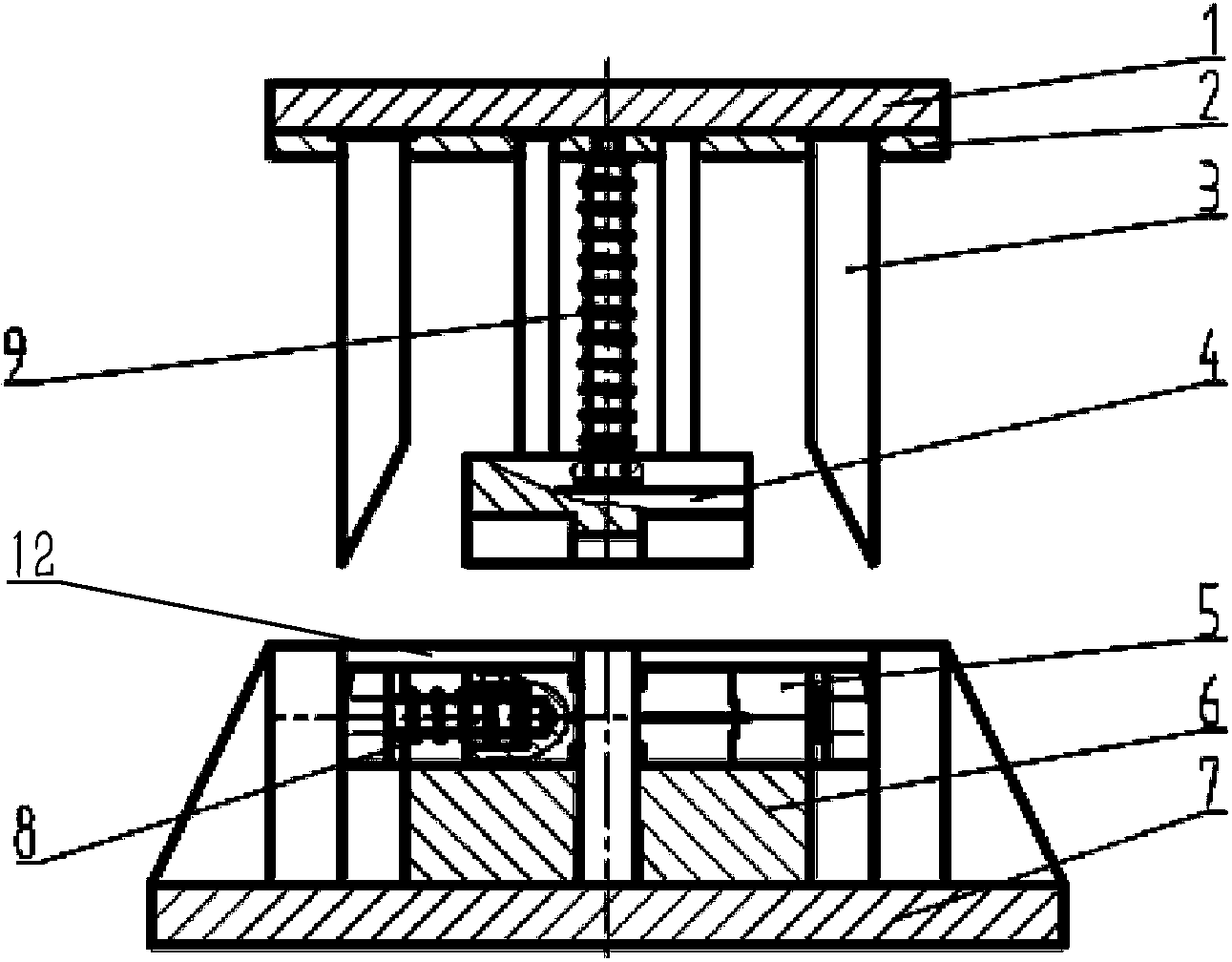
[0028] The embodiment of forging die among the present invention: as Figure 1 to Figure 11 As shown, the forging die is a mold device applied to the plastic forming of metal parts of a rotating body with a small shape in the middle and large ends. It consists of two parts: a forming die and a pressing die. The forging and pressing of the bar is realized by relative pressing. Forming mold is mainly made of main mold body and mold core 5 assembled on it, lockset 10, and compression mold is mainly made of wedge-shaped part 3 and upper mold 4 assembled on pressing plate 2 and its underside. The main mold body is composed of the bottom plate 7 and the upper mold 4 fixed on it. The upper mold 4 and the lower mold 6 are oppositely provided with a semi-cylindrical mold cavity 13. The mold cavity 13 is a necking cavity with wide left and right ends and a narrow middle part. , that is, the mold cavity 13 is divided into a wide section at the left and right ends and a thin section in t...


PUM


Abstract

The invention discloses a forging mould and a forming die of the forging mould. A die cavity of the forming die is a necking cavity which is wide in two ends and narrow in middle, wherein die cores are assembled on two ends of the die cavity by guiding and moving in opposite directions; opposite ends of the two die cores are forming ends; the reverse ends of the two die cores are force transmission ends which are matched with a wedge-shaped surface of a wedge-shaped part and are pressed into the inner end of a guide hole. When the forming die is used, along with lamination of a pressing die to a main die body, the wedge-shaped part is matched with the wedge-shaped surface, so that the forming ends of the two die cores are oppositely pressed, and thus the whole die cores oppositely move in the die cavity; the forming ends of the die cores are used for oppositely extruding and thickening two ends of a bar in the die cavity; the forging and forming can be implemented by extruding the end of the bar by the forming ends of the die cores, namely two ends of the bar are simultaneously thickened and a necking part is processed in the middle of the bar, so that the processing efficiency of the bar for forging and processing thin-neck structures; the processing accuracy is improved.

Description

technical field [0001] The invention relates to a forging die and a forming die thereof. Background technique [0002] At present, when machining rotary parts whose shape is thick at both ends and small in the middle, two methods are usually used: mechanical cutting and forging. Among them, the traditional processing method is mostly carried out by mechanical cutting, especially turning. It is carried out in the same way, that is, assemble the two ends of the bar on the chuck and the thimble respectively, and then align the turning tool clamped on the tool seat to the part to be processed in the middle of the bar, and finally after turning on the machine tool, turn the turning tool The knife is fed in the axial direction of the bar to process the bar into the required shape, but the utilization rate of the material in the mechanical cutting process is low, so that the cut chips are mixed with a large amount of cutting fluid and cutting impurities Such sundries cannot be reu...

Claims


Application Information

Patent Timeline
Patent Type & Authority Applications(China)
IPC IPC(8): B21J13/02
CPCB21J13/02
Inventor 何洲赵飞秦冬雁齐向前王海军杨俊朋
Owner HENAN PINGGAO ELECTRIC
Why Eureka
Try Eureka