Cutting tool for drilling and chamfering steel rail and machining technology thereof

A processing technology and cutting tool technology, which is applied in the field of rail drilling and chamfering tools and its processing technology, can solve the problems of high labor intensity, uneven chamfering, and long time-consuming for operators, and achieve good product quality consistency. Uniform machining of chamfers and improvement of machining efficiency

Inactive Publication Date: 2015-02-04
WUHU CRSIC JIFU RAIL CO LTD
View PDF7 Cites 3 Cited by
  • Summary
  • Abstract
  • Description
  • Claims
  • Application Information

AI Technical Summary

Problems solved by technology

If the drilled hole is not chamfered, stress concentration will occur in the drilled hole, and the rail is prone to cracks at the stress concentration point under load, resulting in rail fracture
[0003] At present, most of the tools are used to drill holes first, and then manually use chamfering milling cutters to chamfer the rails. The disadvantage of manual chamfering is that the chamfering is not uniform, and the stress concentration phenomenon in the bolt holes cannot be well eliminated. The product Consistency is difficult to guarantee; and it takes a long time, the labor intensity of the operator is high, and the production efficiency is low

Method used


Image

  • Cutting tool for drilling and chamfering steel rail and machining technology thereof
  • Cutting tool for drilling and chamfering steel rail and machining technology thereof
  • Cutting tool for drilling and chamfering steel rail and machining technology thereof

Examples


Embodiment Construction

[0024] The specific implementation manner of the present invention will be described in further detail below by describing the embodiments with reference to the accompanying drawings.

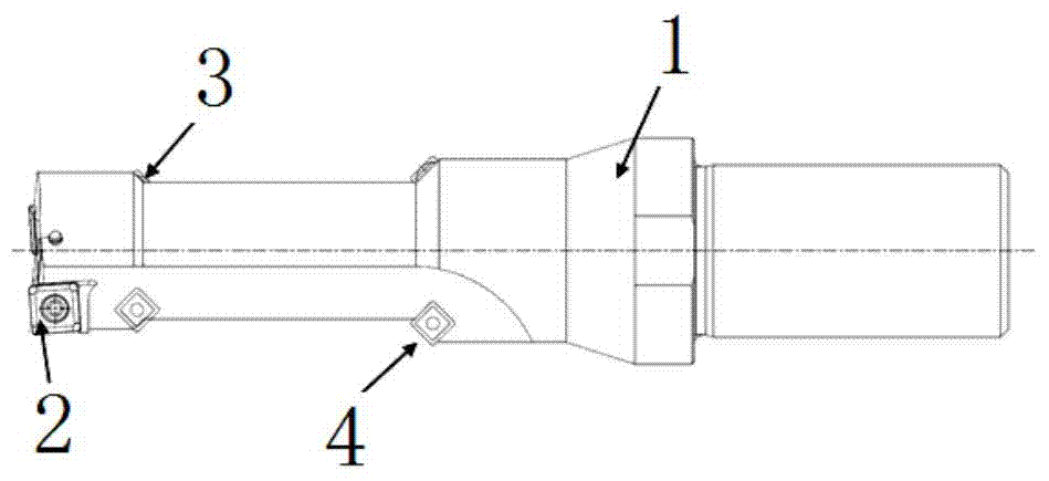
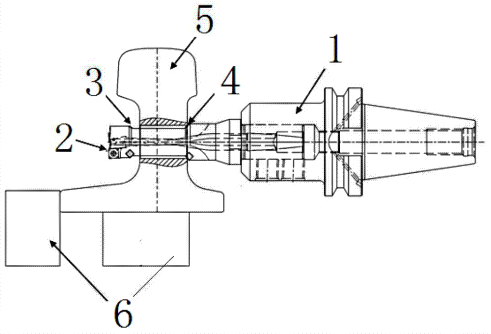
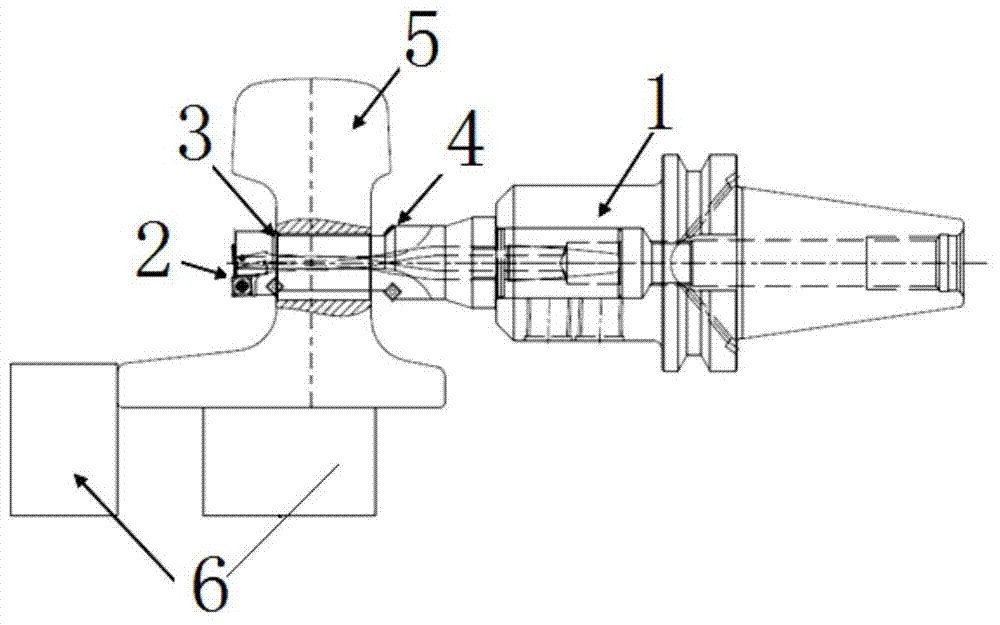
[0025] Such as Figure 1 to Figure 3 As shown, the tool for drilling and chamfering rails includes a cylindrical tool body 1, one end of the tool body 1 is a connector connected to a drilling machine, and the other end of the tool body 1 is a blade structure.

[0026] The blade structure on the tool body 1 includes a first blade 2, a second blade 3, and a third blade 4 which are sequentially arranged from the outer end inward, wherein the first blade 2 is used for drilling and processing the rail 5, and the second blade 3 and the third blade 4 are respectively used for chamfering the edges of the holes on both sides of the rail 5.

[0027] The tool body 1 is divided into three sections from the outside to the inside, namely the outer section, the middle section, and the inner section. The diam...


PUM


Abstract

The invention discloses a cutting tool for drilling and chamfering a steel rail and a machining technology thereof. The cutting tool comprises a cutting tool body, wherein the cutting tool body comprises a first cutting edge, a second cutting edge and a third cutting edge; the first cutting edge is used for drilling the steel rail; the second cutting edge and the third cutting edge are used for chamfering the steel rail; the first cutting edge is positioned at the outermost end of the cutting tool body; the second cutting edge and the third cutting edge are arranged oppositely. The machining technology comprises the following steps of installing the cutting tool on a drilling machine, and positioning and fixing the to-be-machined steel rail; feeding the cutting tool, and drilling the steel rail through the first cutting edge; continuously feeding the cutting tool, and chamfering one side of the steel rail through the third cutting edge; retracting the cutting tool, and chamfering the other side of the steel rail along a rounding path through the second cutting edge; retracting the cutting tool out of the steel rail. According to the cutting tool for drilling and chamfering the steel rail and the machining technology thereof, the machining processes, such as the drilling and two-face chamfering, on the steel rail can be realized, machined chamfers are uniform, the phenomenon of stress concentration is effectively eliminated, the workload of workers is relieved, and the machining efficiency is improved.

Description

technical field [0001] The invention relates to the technical field of rail processing, in particular to a tool for drilling and chamfering a rail and a processing technology thereof. Background technique [0002] In the drilling process of rail parts, chamfering the drilled holes is one of the essential processes. If the drilled hole is not chamfered, stress concentration will occur in the drilled hole, and the rail is prone to cracks at the stress concentration point during load, resulting in rail fracture. [0003] At present, most of the tools are used to drill holes first, and then manually use chamfering milling cutters to chamfer the rails. The disadvantage of manual chamfering is that the chamfering is not uniform, and the stress concentration phenomenon in the bolt holes cannot be well eliminated. The product Consistency is difficult to guarantee; and it takes a long time, the labor intensity of the operator is high, and the production efficiency is low. Contents...

Claims


Application Information

Patent Timeline
Patent Type & Authority Applications(China)
IPC IPC(8): B23B51/08
CPCB23B51/08B23B35/00B23B2251/14
Inventor 李志群钱世山王力红周东东倪明
Owner WUHU CRSIC JIFU RAIL CO LTD
Why Eureka
Try Eureka