Real-time non-contact measuring and compensating device of local deformation quantity

A non-contact measurement and local deformation technology, applied in the direction of measuring/indicating equipment, other manufacturing equipment/tools, metal processing machinery parts, etc., can solve problems such as inconsistent milling depth, increased deformation, and fluctuations in workpiece deformation, and achieve no error accumulation , reduce impact, fast response effect

Active Publication Date: 2015-02-04
SHANGHAI JIAO TONG UNIV +2
View PDF6 Cites 19 Cited by
  • Summary
  • Abstract
  • Description
  • Claims
  • Application Information

AI Technical Summary

Problems solved by technology

There are serious problems in the milling of thin-walled workpieces without real-time deformation measurement compensation control function: (1) When the floating support is not tight, because the milling force of the tool cannot be balanced, the workpiece retreats and the tool falls to form an undercut; (2) When the floating support When it is tightened, the workpiece protrudes toward the opposite direction of the feed, and the tool penetrates too deep to form overcut; (3) The contact between the tool tip and the workpiece changes continuously during milling, resulting in fluctuations in the deformation of the workpiece, and the gradual decrease in the thickness of the workpiece leads to deformation Exacerbated, such as compensating workpiece deformation with a constant compensation amount, it is easy to cause inconsistent milling depth

Method used


Image

  • Real-time non-contact measuring and compensating device of local deformation quantity

Examples


Embodiment Construction

[0014] The technical solution of the present invention will be clearly and completely described below in combination with specific embodiments and accompanying drawings.

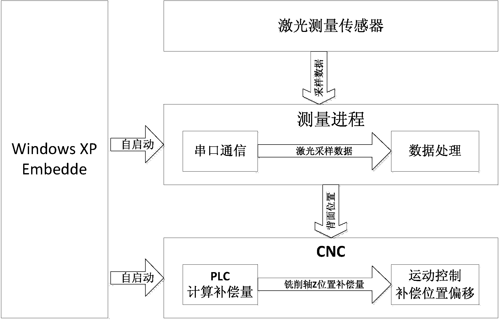
[0015] Such as figure 1 As shown, a real-time non-contact measurement and compensation device for local deformation is characterized in that:

[0016] Including CNC system, real-time laser measurement module and feed axis position compensation module; wherein the positive direction of the laser measurement axis and the forward direction of the target compensation axis are on the same axis but opposite to each other; the target compensation axis is the milling axis equipped with tools;

[0017] (1) Real-time laser measurement module, including laser displacement sensor, computer serial port, and data analysis module;

[0018] Real-time sampling and measurement of the position of the back of the milling point of the workpiece during the milling process by the laser displacement sensor, the position data is re...


PUM


Abstract

The invention provides a real-time non-contact measuring and compensating device of local deformation quantity. According to the technical scheme, the real-time obtaining and position compensating of the deformation quantity can be realized through the control of a laser sensor and a feeding shaft. The real-time non-contact measuring and compensating device comprises a real-time laser measuring module and a feeding shaft position compensating module, wherein the real-time laser measuring module is used for measuring and collecting the position of a workpiece in milling in a cycling mode, the feeding shaft position compensating device is used for obtaining the position compensating quantity of a targeted feeding shaft, and the current position of the targeted feeding shaft can be fast and evenly adjusted. The position compensating quantity of the surface of the workpiece opposite to a tool nose is calculated in real time through tracking the deformation quantity of the thin-wall workpiece, an internally coordinate bias module of a numerical control system is invoked to realize the automatic compensation of the deformation of the workpiece during processing, the real-time non-contact measuring and compensating device has the characteristics of being without error accumulation and rapid in responding speed, the influence of the workpiece deformation to the milling quality can be effectively lowered, and the real-time non-contact measuring and compensating device can be applied in thin-wall workpiece numerical control milling processing.

Description

technical field [0001] The invention belongs to the technical field of mechanical numerical control processing, and in particular relates to a synchronous measurement and compensation device for thin-walled workpiece milling. Background technique [0002] Research shows that in the milling process of thin-walled workpieces, the back of the workpiece needs floating support to provide the back pressing force during milling. When the workpiece is milled, the tool has a dynamically changing milling force on the workpiece. Uneven force and thickness change produce dynamic deformation, which has a decisive impact on the actual milling quality. There are serious problems in the milling of thin-walled workpieces without real-time deformation measurement compensation control function: (1) When the floating support is not tight, because the milling force of the tool cannot be balanced, the workpiece retreats and the tool falls to form an undercut; (2) When the floating support When i...

Claims


Application Information

Patent Timeline
Patent Type & Authority Applications(China)
IPC IPC(8): B23Q17/20B23Q17/24B23Q23/00
CPCB23Q17/20B23Q17/2471B23Q23/00
Inventor 毕庆贞王国庆王宇晗刘钢
Owner SHANGHAI JIAO TONG UNIV
Why Eureka
Try Eureka