Three-linkage synthesis core-pulling device of injection mould

A technology for injection molds and core-pulling devices, which is applied in the field of three-link synthetic core-pulling devices for injection molds, and can solve problems such as prone to failure, increased mold costs, and complex structures

Active Publication Date: 2015-02-04
NINGBO SHUANGLIN MOULD CO LTD
View PDF5 Cites 6 Cited by
  • Summary
  • Abstract
  • Description
  • Claims
  • Application Information

AI Technical Summary

Problems solved by technology

[0002] Injection molds that need to set multiple different core-pulling blocks in a narrow location and perform core-pulling and demoulding. The existing technology uses multiple oil cylinders to drive the respective core-pulling blocks in sequence to perform core-pulling and demoulding. The cost is high, and the internal space of the mold is occupied, which leads to an increase in the shape of the mold, a complex structure, and a further increase in the cost of the mold; in addition, the control of the working order of multiple oil cylinders is strict, and the mold will be damaged if there is a slight error; therefore, the existing technology has Problems and shortcomings of complex structure, large shape, high cost, and prone to failure

Method used


Image

  • Three-linkage synthesis core-pulling device of injection mould
  • Three-linkage synthesis core-pulling device of injection mould
  • Three-linkage synthesis core-pulling device of injection mould

Examples


Embodiment Construction

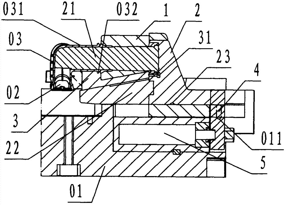
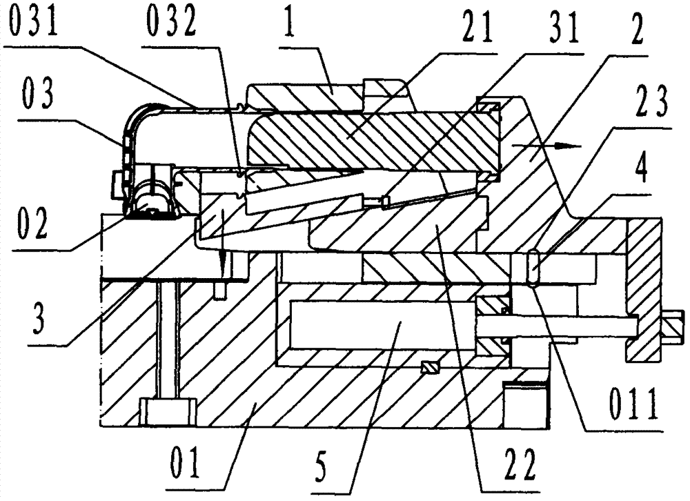
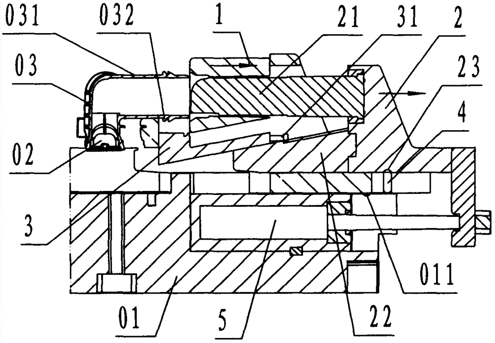
[0021] refer to Figure 1 to Figure 4 , a three-link synthetic core-pulling device for an injection mold of the present invention, comprising a large slider 1, a small slider 2, a lower slider 3, a clutch pin 4, and an oil cylinder 5, wherein: the large slider 1 is block-shaped Steel components, the middle part of the large slider 1 is provided with a slot facing downwards, and the through groove connected in the left and right direction is called a small chute, and the upper part of the left side of the large slider 1 is provided with the outer wall of the pipe interface 031 of the product 03 The profile corresponding to the shape is called the lumen, and the front and back of the lower part of the left side of the large slider 1 is also provided with a profile that matches the undercut structure of the product 03, which is called the horizontal buckle profile; the bottom of the large slider 1 The slide rail with left and right directions is called a large slide rail, and the...


PUM


Abstract

The invention discloses a three-linkage synthesis core-pulling device of an injection mould. The three-linkage synthesis core-pulling device comprises a big sliding block (1), a small sliding block (2), a lower sliding block (3), a separation and reunion pin (4) and an oil cylinder (5), wherein the big sliding block is provided with a pipe cavity, a small sliding groove and a pin groove; the small sliding block is provided with a pipe core, an inclined sliding rail and an upper separation and reunion groove, and the inclined sliding rail is provided with a limiting step; the lower sliding block is provided with a limiting rod; a movable mould support plate is provided with a lower separation and reunion groove; the big sliding block is arranged on the movable mould support plate in a sliding way; the small sliding block is arranged in the small sliding groove in a sliding way; a cylinder body of the oil cylinder is fixedly connected with the movable mould support plate; a piston rod of the oil cylinder is fixedly connected with the small sliding block; the separation and reunion pin is arranged in the pin groove of the big sliding block; when the mould is closed, the lower end of the separation and reunion pin is clamped in the lower separation and reunion groove; when the mould works, the small sliding block is driven by the oil cylinder to enable core-puling to be firstly carried out on the pipe core and the lower sliding block; when the separation and reunion pin is inserted into the upper separation and reunion groove, the big sliding block is connected with the small sliding block, so that core-pulling is carried out on the pipe cavity; therefore, injection mould provided with a plurality of pulling cores at the narrow position achieves the aims of simplifying the structure, reducing the body form, lowering the cost and eliminating failure.

Description

technical field [0001] The invention relates to a core-pulling and demoulding device for an injection mold, in particular to an injection mold used for automobile air-collecting pipe products, which pulls and demoulds three different core-pulling blocks from the reverse buckle structure of the pipe interface of the product A three-link synthetic core-pulling device for an injection mold. Background technique [0002] Injection molds that need to set multiple different core-pulling blocks in a narrow location and perform core-pulling and demoulding. The existing technology uses multiple oil cylinders to drive the respective core-pulling blocks in sequence to perform core-pulling and demoulding. The cost is high, and the internal space of the mold is occupied, which leads to an increase in the shape of the mold, a complex structure, and a further increase in the cost of the mold; in addition, the control of the working order of multiple oil cylinders is strict, and the mold wi...

Claims


Application Information

Patent Timeline
Patent Type & Authority Applications(China)
IPC IPC(8): B29C45/33
CPCB29C45/332B29C2045/334
Inventor 袁贤飞赖忠义泮庭宏顾来法
Owner NINGBO SHUANGLIN MOULD CO LTD
Why Eureka
Try Eureka