
Arrangement of a wheel hub connected to a constant velocity joint provided with a seal device

A constant velocity joint and sealing device technology, applied in the direction of the hub, engine seal, wheel, etc., can solve the problem of not always strong enough magnetic signal, reducing radial extension, and complicated installation.

Active Publication Date: 2015-02-04
AB SKF
View PDF8 Cites 4 Cited by
  • Summary
  • Abstract
  • Description
  • Claims
  • Application Information

AI Technical Summary

Problems solved by technology

However, while satisfactory, this solution reduces the radial extension of the magnetized rubber element used to form the phonic wheel and supported by a separate shroud that is integrated with and constrained by the inner ring
On the one hand, magnetic signals are generated in use which are not always strong enough; on the other hand, there is a reduction in space, especially in the axial direction for the sensor, and the presence of several separate sealing components makes installation more complicated

Method used


Image

  • Arrangement of a wheel hub connected to a constant velocity joint provided with a seal device

Examples


Embodiment Construction

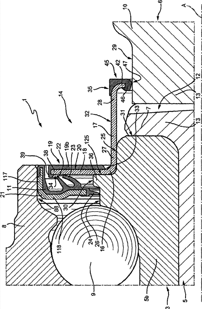
[0017] With reference to the above figures, number 1 designates the whole of the sealing device for the hub assembly 3, the inner ring 5 of which is operatively associated with the constant velocity joint 6 to rotate therewith, which is known and thus convenient For sake of illustration only part is shown. The hub assembly 3 further comprises: an outer ring 8 mounted coaxially and concentrically with the ring 5 , radially outside the ring 5 ; and a plurality of rolling bodies 9 interposed between the rings 5 ​​and 8 . The inner ring 5 comprises a ring 5b (insertion ring or "SIR") made as a separate element, axially blocked by a bead 7 and externally delimited by an outer cylindrical side surface 26; Meanwhile, the constant velocity joint 6 includes an outer ring 10 (the only part of the constant velocity joint 6 shown in the drawings), which has an outer cylindrical side surface 29 and is generally arranged substantially at the same level as the inner ring 5. The shaft also h...


PUM


Abstract

An arrangement (1) including a stretch (30) of a radially outer lateral surface (26) of an inner ring of wheel hub (3) on which an annular step (25) is obtained on the side of a constant velocity joint (6), said step adapted to receive a first shield (16), a flange portion (18) of which radially extends so as to protrude towards an outer ring (8) of a wheel hub, in front of a flange portion (118) of a second shield, from a first end (27) of a sleeve portion (17) of the first shield facing on the side opposite of the constant velocity joint and which axially extends so as to protrude from the inner ring (5) and towards the joint (6) thus defining a tubular element (32) arranged straddling wheel hub (3) and an outer ring (10) of the constant velocity joint, and has an opposite second end (28), supporting an annular seal (35); an annular signal generating insert (19b) covers a face (20) of the flange portion of the first shield facing the joint, so that a radially inner annular part (33) of face (20) defines a thrust shoulder for mounting the first shield.

Description

technical field [0001] The present invention relates to a sealing device for a hub assembly connected to a constant velocity joint and a corresponding arrangement therein, with low operating friction and a simplified structure. Background technique [0002] The hub assembly on the one hand supports the wheel and, if the wheel is a drive wheel, is angularly connected to the associated constant velocity joint for the transmission of drive torque from the drive shaft to the wheel itself. The hub assembly has an axis of rotation and includes an inner ring and an outer ring coaxial with each other and with the axis of rotation, the inner ring and the outer ring being rotatable relative to each other due to interposition of two rows of rolling elements therebetween. [0003] The inner ring is a flanged inner ring to attach the wheel to the assembly and includes: [0004] flange, transverse to the axis of rotation, [0005] a journal extending along the axis of rotation and integ...

Claims


Application Information

Patent Timeline
Patent Type & Authority Applications(China)
IPC IPC(8): B60B27/00B60B35/00F16J15/00
CPCF16C41/007F16C2326/02F16C33/805F16C33/768F16C33/583F16C19/186B60B27/0073F16C33/7883F16D2300/08B60B27/0036F16D1/033
Inventor D·达克F·莫雷罗
Owner AB SKF
Learn More