Gravity compensation device for solar wing low temperature unfolding experiment

A technology of gravity compensation and the sun, which is applied in the field of deep space exploration, can solve problems that affect the reliability of deployment, many moving parts, and inconsistent step numbers of deployment and retraction, so as to reduce the requirement of spatial relative position accuracy and ensure spatial relative position accuracy , Adjust the effect of convenient and quick operation

Active Publication Date: 2015-02-04
BEIJING SATELLITE MFG FACTORY
View PDF5 Cites 28 Cited by
  • Summary
  • Abstract
  • Description
  • Claims
  • Application Information

AI Technical Summary

Problems solved by technology

[0003] The traditional solar wing deployment gravity compensation device includes the balloon suspension gravity compensation type and the double guide rail gravity compensation type: the former may rupture the balloon inner bag plastic in a low temperature environment, and the inertial force of the balloon may cause the motor to fold in place signal to fail to trigger when the end of the solar wing is folded , the number of steps in the final deployment and retraction is inconsistent, which affects the reliability of deployment; the latter

Method used


Image

  • Gravity compensation device for solar wing low temperature unfolding experiment
  • Gravity compensation device for solar wing low temperature unfolding experiment
  • Gravity compensation device for solar wing low temperature unfolding experiment

Examples


Embodiment Construction

[0031] The specific implementation manners of the present invention will be further described in detail below in conjunction with the accompanying drawings.

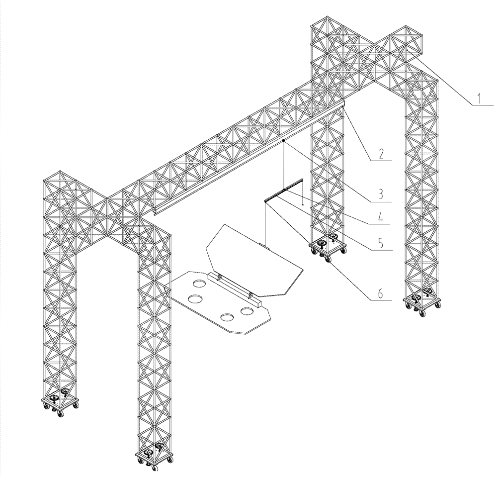
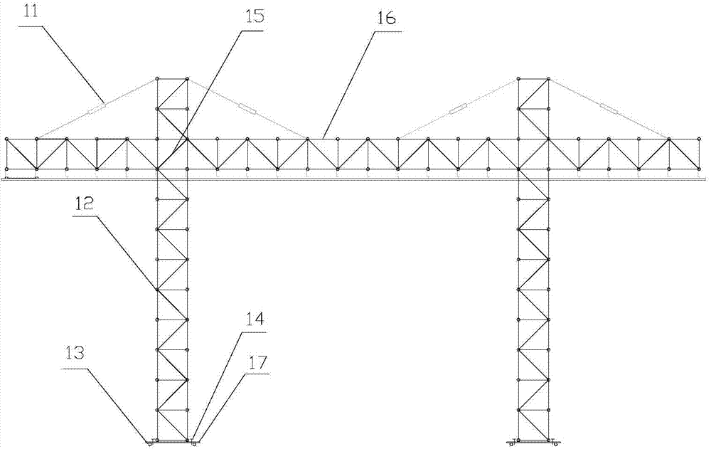
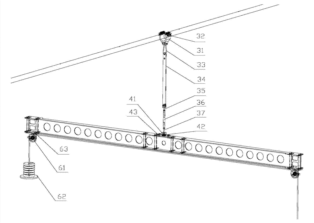
[0032] The gravity compensating device of the invention mainly includes: the unfolding frame assembly 1, the guide rail assembly 2, the pulley assembly 3, the horizontal rotation assembly 4, the main beam assembly 5 and the fixed pulley assembly 6, such as figure 1 shown. Use the pulley assembly 3 to realize the movement of the center of mass of the solar wing in the direction of gravity, use the horizontal rotation assembly 4 to realize the rotation of the main beam assembly 5 on the horizontal plane, and use the fixed pulley assembly 6 to realize the vertical movement of the solar wing. Through these three points Fit the trajectory of the center of mass of the solar wing to achieve various attitude adjustments, and realize 1 / 6 gravity or zero gravity simulation by changing the mass of the counterweight in the fixed pul...


PUM


Abstract

A gravity compensation device for solar wing low temperature unfolding experiment is capable of realizing one sixth gravity compensation and zero gravity compensation of solar wing at a temperature of -120 DEG C. The device also can carry out solar wing multi-angle repeated unfolding and folding experiments in a limit position by simulating a landing situation when the included angle between the moon surface and the horizontal plane is 15 degrees. A balance rod is adopted in the device to carry out gravity compensation, and is completely made of metals so as to adapt to the low temperature environment. The three-dimensional trace movement of the mass center of a solar wing is completed by the swinging of a guide rail and a suspension rod; the conventional bidirectional guide rail structure composed of a solar wing vertical guide rail and a solar wing horizontal guide rail is broken through, thus the system complexity is reduced, and the movement reliability is improved. A horizontal rotation assembly is adopted to enable the main beam to freely rotate in a horizontal plane, and the gravity compensation technology is broken through when the included angle between a solar wing and the horizontal plane is 15 degrees namely the extreme working condition. A pulley and a pulley structure are adopted to reduce the movement resistance. A main beam having an I-shaped aluminum structure is adopted, the weight of movable parts is reduced, and thus the inertia force during the folding and unfolding process of a solar wing is effectively reduced.

Description

technical field [0001] The invention relates to a gravity compensation device, in particular to a gravity compensation device used for low-temperature deployment tests of solar wings, which can realize the deployment of various postures of the solar wing in a -120° low-temperature environment and a low-gravity environment, and belongs to the field of deep space exploration . Background technique [0002] In the process of developing the solar wing of a deep space probe, it is necessary to simulate the working conditions on the surface of the moon to conduct 1 / 6 gravity and zero gravity deployment tests of the solar wing in a low temperature environment of -120°, and at the same time, it is necessary to simulate the extreme position of the probe when it lands, that is, the solar wing It is 15° from the horizontal plane, and it can be unfolded and retracted repeatedly in multiple postures and angles. [0003] The traditional solar wing deployment gravity compensation device i...

Claims


Application Information

Patent Timeline
IPC IPC(8): B66C17/04B66C17/06
CPCB66C17/04B66C17/06
Inventor 何鹏鹏徐立力郑树杰徐燕菱程泽赵琳娜赖小明
Owner BEIJING SATELLITE MFG FACTORY
Why Eureka
Try Eureka