Freeform surface building grid division method based on self-defined element method

A grid division and self-definition technology, applied in 3D modeling, image data processing, instruments, etc., can solve the problems of not being able to meet the aesthetic requirements of grid architecture, grid unevenness, and relying on the design experience of engineers to meet Aesthetic requirements and visual effects, diverse grid forms, flexible and controllable methods

Inactive Publication Date: 2015-02-04
ZHEJIANG UNIV
View PDF2 Cites 6 Cited by
  • Summary
  • Abstract
  • Description
  • Claims
  • Application Information

AI Technical Summary

Problems solved by technology

The manual division method means that engineers use geometric modeling software to manually divide a specific project, which has low efficiency, poor versatility, and relies on the design experience of engineers, so it is difficult to be widely used as a general technical method.
The finite element method uses the traditional finite element meshing technology to automatically mesh the building surface. However, due to the differences between the architectural mesh and the finite element meshing requirements, it is often difficult to use the finite element method alone for building meshing. Causes problems such as disordered nodes and uneven grids, which cannot meet the architectural aesthetic requirements of uniform and smooth grids

Method used


Image

  • Freeform surface building grid division method based on self-defined element method
  • Freeform surface building grid division method based on self-defined element method
  • Freeform surface building grid division method based on self-defined element method

Examples


Embodiment 1

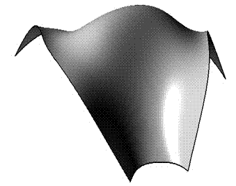
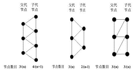
[0030] A free-form surface building model, such as figure 1 Shown. Surface size along the parametric domain u The direction changes regularly, and the custom unit types such as figure 2 Shown.

[0031] According to the surface size characteristics, select the parameter domain u The direction is used as the node advancing direction.

[0032] The number of advance steps is 27, and the parameter line of the node of each generation is obtained. The initial number of nodes is determined to be 10, along with u =0 Parameter line layout, dichotomy loop adjusts the node parameter coordinates, so that the surface distance under the initial node Riemann metric is equal.

[0033] Select the element type according to the surface features of the parametric line where the upper and lower nodes are located. When the surface is expanded, the meristematic unit is automatically selected to increase the number of nodes in the next generation; when the surface is contracted, the symbiotic unit is auto...


PUM


Abstract

The invention discloses a freeform surface building grid division method based on a self-defined element method. According to the grid division method, grid nodes serve as objects to advance. The method comprises steps of determining a node advancing parameter direction, defining, selecting and assembling grid units and mapping parameter grids. As for determining of the node advancing parameter direction, the parameter direction with obvious surface shape feature changes is selected to serve as the node advancing direction. As for defining, selecting and assembling of the grid units, self definition of grid units are carried out in a parameter domain, unit selection and assembly are carried out according to the surface features, and node parameter coordinates and topology information are determined. The parameter grids are mapped to the freeform surface to form a space grid. According to the method of the invention, the building grids of any complicated freeform surfaces can be automatically divided, the generated grids have various forms and uniform size, aesthetic demands and visual effects of the building can be met, the method is flexible and controllable, and universality is strong.

Description

Technical field [0001] The invention belongs to the field of grid division, and particularly relates to an automatic construction grid division method of a free-form surface NURBS model. Background technique [0002] In recent years, with the development of architectural design and construction level and the improvement of people’s aesthetic requirements, regular and traditional curved surfaces can no longer meet people’s requirements for architectural modeling, and free-form surface grid structures with novel structures and smooth lines are increasingly favored by architects . Due to the free surface of this kind of structure, it is complicated and changeable, and the traditional method of arrangement of rods has been stretched to face this kind of structure. Therefore, how to make a reasonable grid division is the key to whether this type of structure can be realized, whether the architectural shape is beautiful, and whether the structural performance is good. [0003] At pres...

Claims


Application Information

Patent Timeline
Patent Type & Authority Applications(China)
IPC IPC(8): G06T17/30
CPCG06T17/30
Inventor 高博青江存
Owner ZHEJIANG UNIV
Why Eureka
Try Eureka