Traction mechanism suitable for hull type floating nuclear power plant

A traction mechanism and nuclear power plant technology, applied in the field of floating nuclear power plants, can solve problems such as unfavorable reactors and large shaking of floating nuclear power plants, and achieve the effects of reducing impact force, reducing up and down fluctuations, and avoiding shaking

Active Publication Date: 2016-11-09
NUCLEAR POWER INSTITUTE OF CHINA
View PDF5 Cites 0 Cited by
  • Summary
  • Abstract
  • Description
  • Claims
  • Application Information

AI Technical Summary

Problems solved by technology

[0004] In the process of transporting the floating nuclear power plant to the designated location, long-distance transportation is required, and when cornering or when waves hit, the floating nuclear power plant may shake a lot, which is not good for the reactor on the floating nuclear power plant

Method used


Image

  • Traction mechanism suitable for hull type floating nuclear power plant
  • Traction mechanism suitable for hull type floating nuclear power plant
  • Traction mechanism suitable for hull type floating nuclear power plant

Examples


Embodiment 1

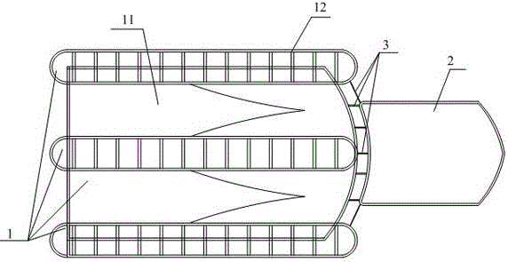
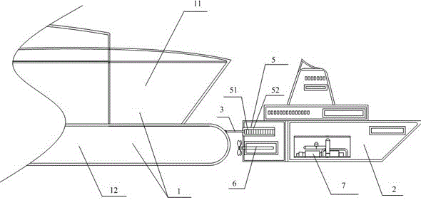
[0029] Such as figure 1 with figure 2 As shown, the towing mechanism suitable for hull-type floating nuclear power plants includes a towing ship 2 and a connecting device, and the connecting device includes a plurality of connecting hinge rods 3 connected between the head of the floating nuclear power plant 1 and the tail of the towing ship 2, and the connecting hinges The rod 3 is connected to the head of the floating nuclear power plant 1 through the fixed joint 4, and the tail of the tow ship 2 is connected to the hinge rod connection device 5, and a plurality of connecting hinge rods 3 are connected to the head of the floating nuclear power plant 1 and the tail of the tow ship 2 in a dispersed manner. The connection means that there are multiple connecting points between the hinge rods 3 and the head of the floating nuclear power plant 1 and the tow ship 2, specifically: there are multiple hinge rod connection devices 5 at the tail of the tow ship 2, which are distributed...

Embodiment 2

[0031] On the basis of Embodiment 1, the structure of the connecting hinge bar 3 is further limited in this embodiment:

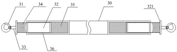
[0032] Such as image 3 with Figure 5 As shown, the connecting hinge rod 3 includes a rod body 30, an anchor hook 31, a pressing block 32, a connecting rod 33, a damping spring 34, a rubber damping block 35, and a rubber damping layer 36. The rod body 30 of the connecting hinge rod 3 has two The end is provided with a shock absorbing cavity 37, and the rubber damping block 35 is arranged in the shock absorbing cavity 37, and the pressure block 32 partly extends into the shock absorbing cavity 37 to contact with the rubber damping block 35, and is partially located in the shock absorbing cavity. Outside the cavity 37, and the pressure block 32 and the rubber damping block 35 are arranged side by side along the length direction of the connecting rod body 30, the pressing block 32 is closer to the end of the rod body 30, and the rubber damping block 35 is cl...

Embodiment 3

[0037] On the basis of any of the above-mentioned embodiments, the structure of the hinge rod connecting device 5 is further limited in this embodiment:

[0038] Described hinge link connecting device 5 comprises the cavity 51 that is arranged on the stern of towing ship 2 for accommodating the end of connecting hinge 3 and is arranged on the retraction mechanism 52 in cavity 51; The rear end of the cavity 51 extends into the cavity 51; the front end of the retraction mechanism 52 is fixedly connected to the front cavity wall of the cavity 51, and the rear end is fixedly connected to the connecting hinge rod 3, which can be connected to it when cornering and under the impact of waves. The end of the connecting hinge rod 3 shrinks into the cavity to limit the up and down swing of the connecting hinge rod 3, thereby generating a pulling force on the floating nuclear power plant 1 and reducing the up and down fluctuation of the floating nuclear power plant 1. In this embodiment, ...


PUM


Abstract

The invention relates to the technical field of floating nuclear power stations, and particularly discloses a traction mechanism suitable for a hull type floating nuclear power station. The traction mechanism comprises a traction ship and a connecting device, wherein the connecting device comprises a plurality of connecting hinge rods which are connected between the head part of the floating nuclear power station and the tail part of the traction ship; the connecting hinge rods are connected to the head part of the floating nuclear power station and the tail part of the traction ship in a scattered manner and are provided with damping devices; hinge rod connecting devices comprise cavities and contraction mechanisms; the cavities are accommodated in the end parts of the connecting hinge rods; the contraction mechanisms are used for contracting the end parts of the connecting hinge rods into the cavities. The relative position of the floating power station and the traction ship does not change greatly during turning and under the impact of seawater and the inertia of the mechanism, larger shake of the floating nuclear power station is avoided, and the impact force of the floating nuclear power station to the traction ship is reduced when the traction ship stops.

Description

technical field [0001] The invention relates to the technical field of floating nuclear power plants, in particular to a traction mechanism suitable for a hull-type floating nuclear power plant. Background technique [0002] Floating nuclear power plants are built on the sea and are divided into platform-type floating nuclear power plants and hull-type floating nuclear power plants. Floating nuclear power plants can be used for power generation, desalination of seawater, heating, and can meet regional power supply, district heating, offshore oil exploitation, chemical industry, polar or remote areas, isolated islands and other special needs. [0003] As far as my country is concerned, floating nuclear power plants can meet the large-scale energy demand of islands and oil drilling platforms far away from the mainland, and provide abundant energy for the development of coastal islands and deep-sea oil and gas development in my country in terms of power supply and seawater desa...

Claims


Application Information

Patent Timeline
Patent Type & Authority Patents(China)
IPC IPC(8): G21D1/02
CPCG21D1/02Y02E30/00
Inventor 李松许余李卓群罗琦刘聪陈智曾未明哲东姚维华
Owner NUCLEAR POWER INSTITUTE OF CHINA
Why Eureka
Try Eureka