PWM control circuit of radar antenna

A technology for controlling circuits and radar antennas, which can be used in excitation or armature current control, electrical components, output power conversion devices, etc., to solve problems such as loss, and achieve high integration, small size, and stable performance.

Inactive Publication Date: 2015-02-04
CHENGDU RUIXIN TECH
View PDF2 Cites 1 Cited by
  • Summary
  • Abstract
  • Description
  • Claims
  • Application Information

AI Technical Summary

Problems solved by technology

It has high integration, small size, stable performance, and can drive the grid with a single power supply, realizes the servo control of the radar antenna, solves the problem of dynamic bootstrapping, and overcomes the problem that the bipolar PWM circuit still remains when the motor stops rotating. The disadvantage of loss improves the speed of the radar antenna and the efficiency of the power conversion circuit

Method used


Image

  • PWM control circuit of radar antenna
  • PWM control circuit of radar antenna

Examples


Embodiment Construction

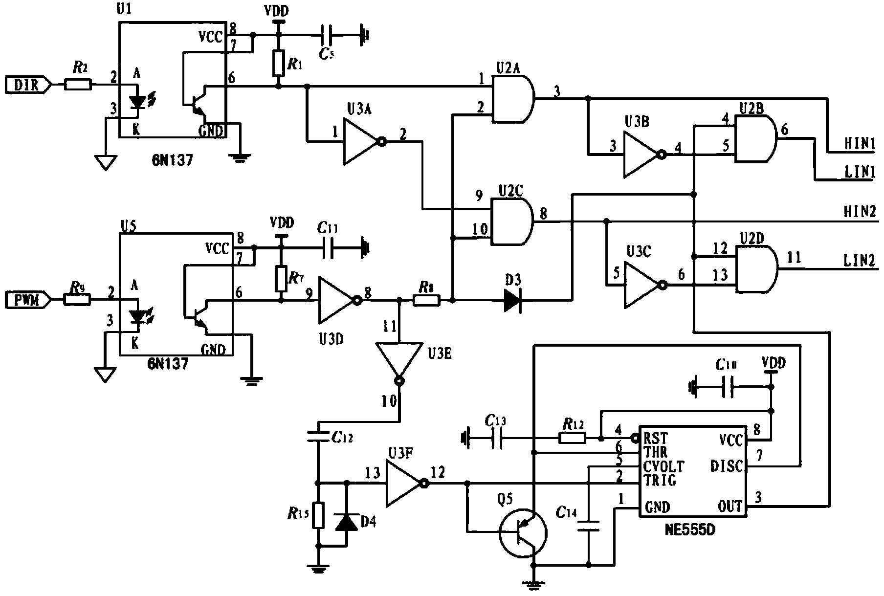
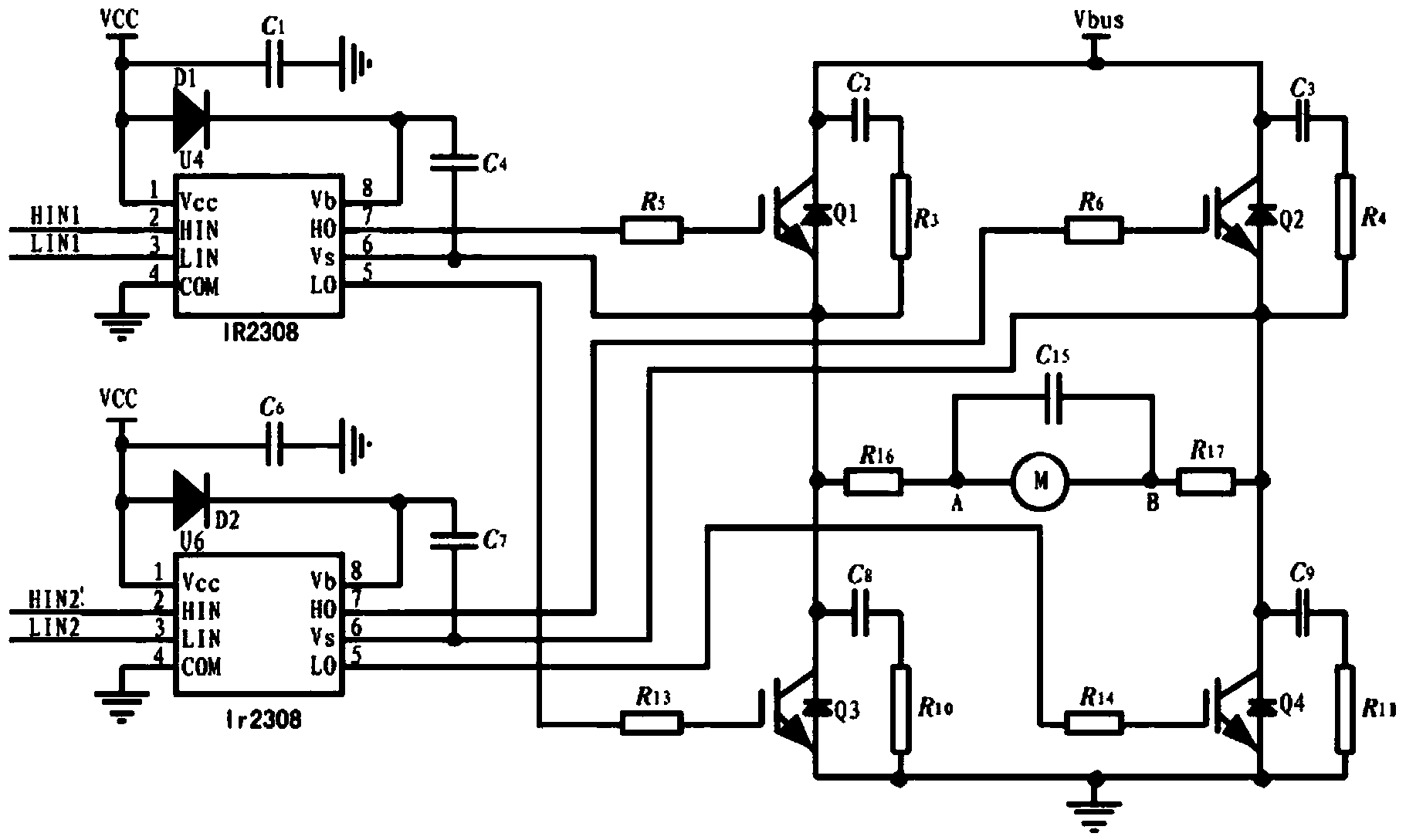
[0019] Such as figure 1 and figure 2 As shown, a PWM control circuit of a radar antenna is characterized in that: it includes a logic distribution circuit and a drive and power conversion circuit electrically connected to the output of the logic distribution circuit, and the logic distribution circuit includes two photoelectric isolators and NE555 circuits , the drive and power conversion circuit includes two IR2308 chips and an H-bridge drive and power conversion circuit composed of IGBTs connected to their output terminals.

[0020] In this embodiment, the two photoelectric isolators are photoelectric isolation chips of model 6N137.

[0021] In this embodiment, one of the two photoelectric isolators inputs a direction signal, and the other inputs a pulse width modulation signal.

[0022] In this embodiment, the output terminals of the two photoelectric isolators are connected to a logic signal conversion circuit composed of a NOT gate and an AND gate.

[0023] In this em...


PUM


Abstract

The invention discloses a PWM control circuit of a radar antenna. The PWM control circuit is characterized by comprising a logical distribution circuit and a drive and power conversion circuit which is electrically connected with the output end of the logical distribution circuit; the logical distribution circuit comprises two optoelectronic isolators and an NE555 circuit; the drive and power conversion circuit comprises two IR2308 chips and an H bridge drive and power conversion circuit which is composed of IGBTs and connected with the output ends of the two IR2308 chips. According to the PWM control circuit of the radar antenna, a unipolar PWM logical distribution circuit based on the dynamic bootstrap technique is designed, and the unipolar PWM logical distribution circuit is high in integrity, small in volume, stable in performance, and capable of driving a gate by use of a single power source; as a result, servo control on the radar antenna is realized, the dynamic bootstrap problem is solved, the defect that a bipolar PWM circuit still has loss after a motor stops rotating, and the rotating speed of the radar antenna is increased and the efficiency of the power conversion circuit is improved.

Description

technical field [0001] The invention relates to the technical field of radar control, in particular to a PWM control circuit of a radar antenna. Background technique [0002] With the development of high-power semiconductor technology, pulse width modulation (PWM) technology composed of fully controlled power electronic devices has been widely used in radar antenna control systems. The radar antenna control system generally uses pulse width modulation (PWM) technology to realize motor speed regulation, and the H-bridge power conversion circuit composed of power transistors is often used to drive the servo motor. According to the difference in polarity of the voltage applied to both ends of the armature within a switching cycle, it is divided into bipolar and unipolar mode PWM. [0003] In a bipolar PWM power converter, the control signals of the upper and lower bridge arms on the same side are opposite PWM signals; while the control signals of the upper and lower bridge arm...

Claims


Application Information

Patent Timeline
IPC IPC(8): H02M1/088H02P7/29
CPCH02M1/088H02P7/29
Inventor 张洪军廖云龙赵永亮
Owner CHENGDU RUIXIN TECH
Why Eureka
Try Eureka