
Phase shift full bridge switching converter

A switching converter, phase-shifting full-bridge technology, applied in instruments, converting DC power input to DC power output, adjusting electrical variables, etc. The effect of reducing the possibility and the reliability of the circuit is obvious

Active Publication Date: 2015-02-04
SOUTHEAST UNIV
View PDF4 Cites 5 Cited by
  • Summary
  • Abstract
  • Description
  • Claims
  • Application Information

AI Technical Summary

Problems solved by technology

The current design for reliability is mainly aimed at the failure of the soft switch of the lagging arm under light load conditions, while ignoring the problem of the Miller platform extension of the leading arm under heavy load conditions

Method used


Image

  • Phase shift full bridge switching converter
  • Phase shift full bridge switching converter
  • Phase shift full bridge switching converter

Examples


Embodiment Construction

[0031] Below in conjunction with accompanying drawing, the technical scheme of invention is described in detail:

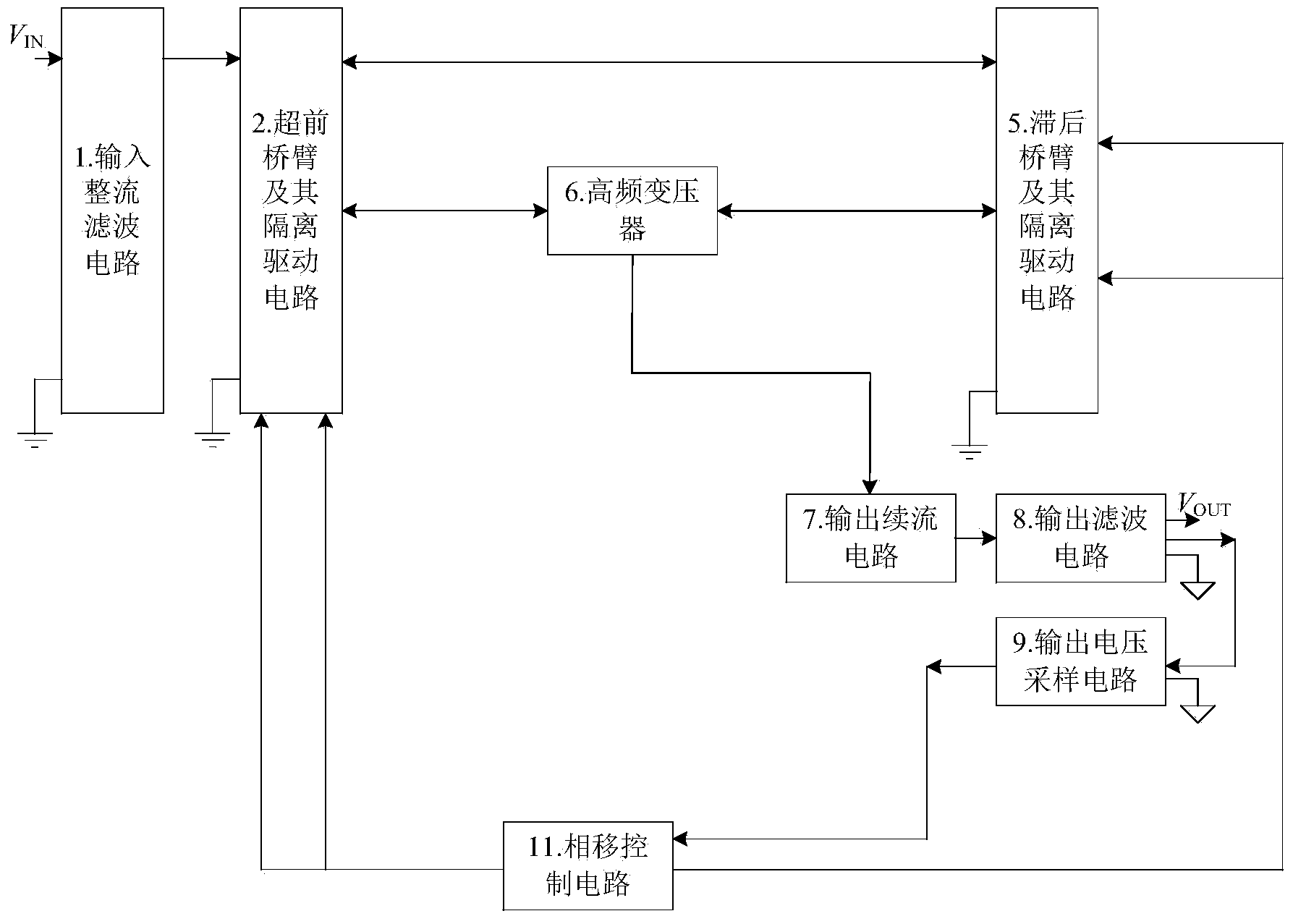
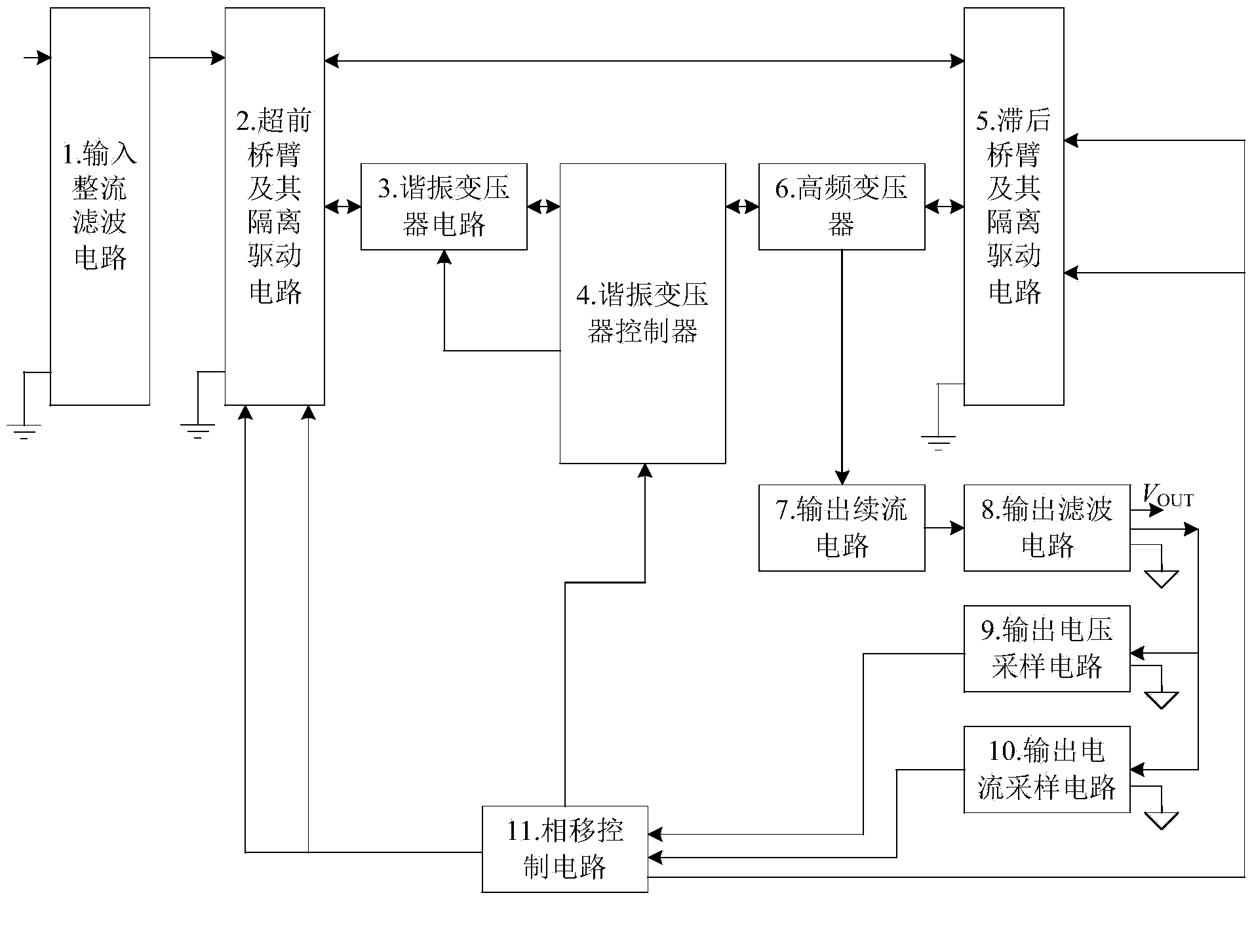
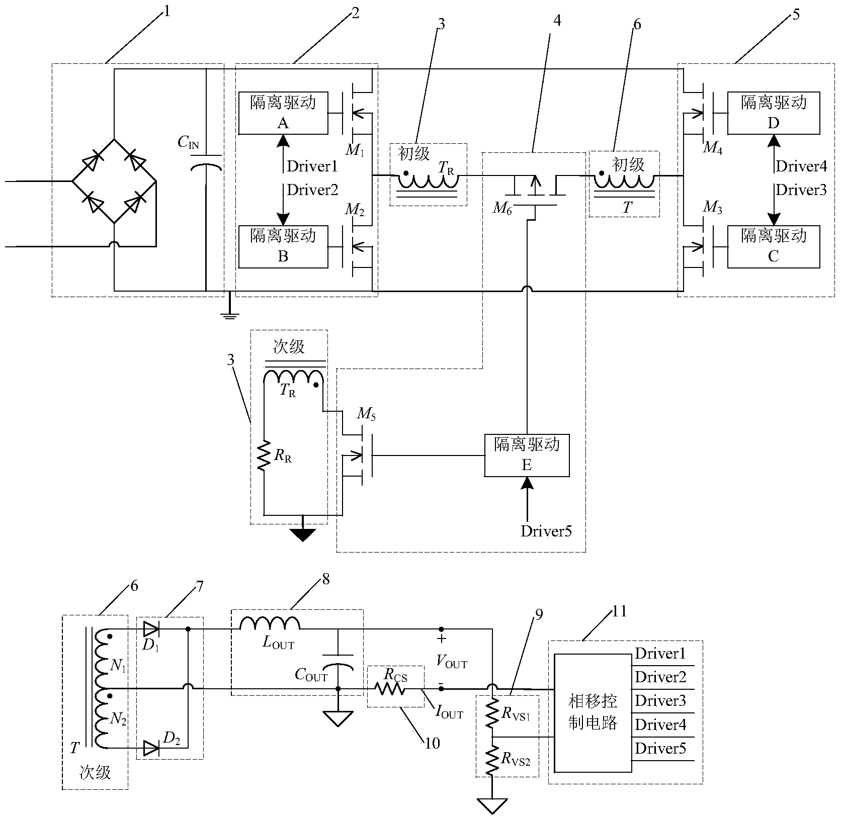
[0032] figure 1 It is the existing technology including input rectification filter circuit 1, leading bridge arm and its isolation drive circuit 2, lagging bridge arm and its isolation drive circuit 5, high frequency transformer 6, output freewheeling circuit 7, output filter circuit 8, output voltage sampling Circuit 9 and phase-shift control circuit 11 constitute a basic phase-shift full-bridge switching converter. The invention is figure 1 On the basis of the prior art, a resonant transformer circuit 3, a resonant transformer controller 4 and an output current sampling circuit 10 are added, such as figure 2 . figure 1 and figure 2 The double-headed arrows shown in indicate that the current will flow in different directions at different times.

[0033] Such as image 3, the input rectification and filtering circuit 1 is composed of four diodes to form a ...


PUM


Abstract

The invention discloses a phase shift full bridge switching converter. The basic phase shift full bridge switching converter structure comprises an input rectifier filter circuit, an advance bridge arm and an isolation drive circuit thereof, a lag bridge arm and an isolation drive circuit thereof, a high-frequency transformer, an output fly-back circuit, an output filter circuit, an output voltage sampling circuit and a phase shift controller, and is characterized in that a resonant transformer circuit for substituting a resonant inductor and a resonant transformer controller using a power semiconductor switching device are additionally arranged between the advance bridge arm as well as the isolation drive circuit thereof and the high frequency transformer, and control is performed by the phase shift control circuit. The output current sampling circuit is additionally arranged between the output filter circuit output ground and the phase shift controller, so that the reliability of the phase shift full bridge converter is greatly improved.

Description

technical field [0001] The invention relates to a switching converter, in particular to a phase-shifting full-bridge switching converter, which can improve the reliability of a power semiconductor switching device. Background technique [0002] Currently, in the application of high-power switching converters, isolated full-bridge converters are the most common, because the main advantages of isolated full-bridge converters are: [0003] 1. As a variant of the Buck converter, the efficiency of the full bridge converter is very high; [0004] 2. The voltage on the primary side of the high-frequency transformer is positive and negative symmetrical, and there is no problem of magnetic bias; [0005] 3. When the drain-source voltage of the power MOSFET is the highest, it is equal to the bus voltage, and the voltage stress on the power MOSFET of the full-bridge converter is low; [0006] The mainstream control methods of the full-bridge converter are divided into hard switching ...

Claims


Application Information

Patent Timeline
Patent Type & Authority Applications(China)
IPC IPC(8): H02M3/335
CPCH02M1/38H02M3/33576H02M1/0058Y02B70/10
Inventor 钱钦松俞居正朱俊杰郭小强孙伟锋陆生礼时龙兴
Owner SOUTHEAST UNIV
Learn More