Control circuit and method for x-ray high voltage generator, series resonant converter

A series resonance, control circuit technology, applied in X-ray equipment, control/regulation systems, high-efficiency power electronic conversion, etc., to achieve the effect of reducing possibility, improving reliability, and maintaining adaptability

Active Publication Date: 2017-09-29
SHANGHAI UNITED IMAGING HEALTHCARE +1
View PDF8 Cites 0 Cited by
  • Summary
  • Abstract
  • Description
  • Claims
  • Application Information

AI Technical Summary

Problems solved by technology

[0009] The technical problem to be solved by the present invention is to provide a control circuit for the series resonant inverter of the X-ray high voltage generator, which overcomes the problem of the modulation mode of the existing series resonant converter

Method used


Image

  • Control circuit and method for x-ray high voltage generator, series resonant converter
  • Control circuit and method for x-ray high voltage generator, series resonant converter
  • Control circuit and method for x-ray high voltage generator, series resonant converter

Examples


no. 1 example

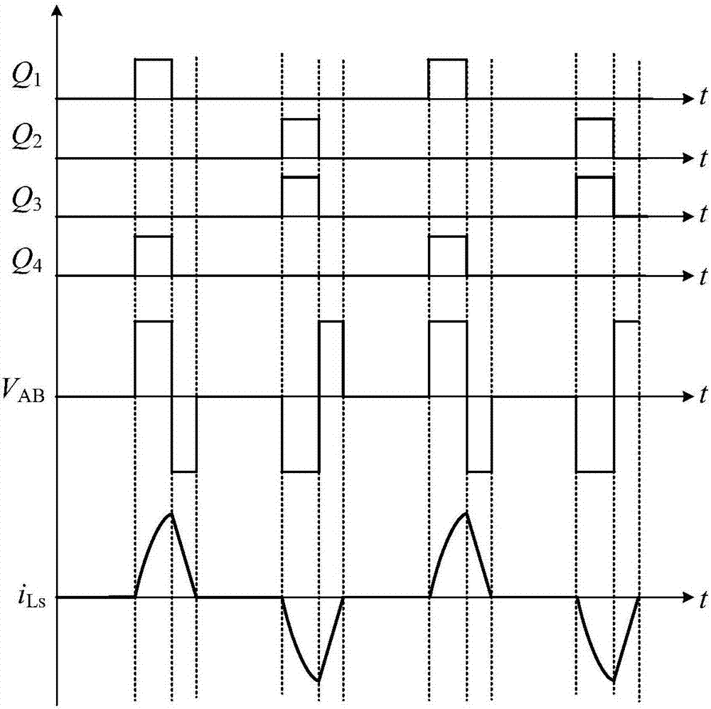
[0041] According to this embodiment, the leading bridge arm of the inverter circuit 51 adopts bipolar modulation, and the opening of the lagging bridge arm is the same as that of the leading bridge arm, and the shutdown signal is obtained by detecting the zero signal of the series resonant circuit current Achieved. Image 6 is a modulation waveform diagram of the series resonant inverter according to the first embodiment of the present invention. refer to Image 6 As shown, the first drive signal S1 and the second drive signal S2 constitute bipolar modulation; the third drive signal S3 drives the conduction moment of the third switching device Q3 and the second drive signal S2 drives the conduction of the second switch device Q2 The time is the same, the turn-on time of the fourth driving signal S4 driving the fourth switching device Q4 is the same as the turning-on time of the first driving signal S1 driving the first switching device Q1 . In addition, the turn-off time of ...

no. 2 example

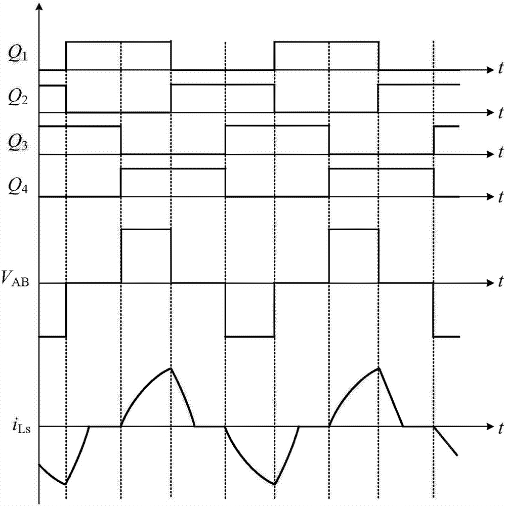
[0054] According to this embodiment, the switching devices Q1 and Q3 of the inverter circuit 51 adopt bipolar modulation, the switching device Q2 and the switching device Q3 have the same conduction time, the switching device Q4 and the switching device Q1 have the same conduction time, and the second switch The turn-off signal of the device Q2 and the fourth switching device Q4 is realized by detecting the zero signal of the resonant cavity current of the series resonant converter. Figure 8 is a modulation waveform diagram of the series resonant converter according to the second embodiment of the present invention. refer to Figure 8 As shown, the first driving signal S1 and the third driving signal S3 constitute bipolar modulation; the second driving signal S2 drives the conduction moment of the second switching device Q2 and the third driving signal S3 drives the third switching device Q3 to conduct The time is the same, the turn-on time of the fourth driving signal S4 dr...


PUM


Abstract

The invention provides a control circuit and a control method of an X-ray high-voltage generator and a series resonant converter. The inverter circuit of the series resonant converter includes a leading bridge arm and a lagging bridge arm, the leading bridge arm includes first and second switching devices, the lagging bridge arm includes third and fourth switching devices, the control circuit includes a driving circuit, and provides the first to the fourth driving signals to the first to the fourth switching devices. The first and second drive signals constitute bipolar modulation, the turn-on moments of the third and fourth drive signals are respectively the same as the turn-on moments of the second and first drive signals, and the turn-off moments of the third and fourth drive signals It is determined according to the resonant cavity current of the series resonant converter; or the first and third drive signals form bipolar modulation, and the conduction moments of the second and fourth drive signals are respectively the same as the conduction moments of the third and first drive signals Similarly, the turn-off time of the second and fourth driving signals is determined according to the resonant cavity current of the series resonant converter.

Description

technical field [0001] The present invention mainly relates to an X-ray high-voltage generator, in particular to a control circuit and a control method for a series resonant converter of the X-ray high-voltage generator. Background technique [0002] X-ray high-voltage generators are used in X-ray therapy equipment, X-ray diagnostic equipment, X-ray computed tomography (CT), positron emission computed tomography (PET-CT) and other equipment. In the inverter circuit of the high-power X-ray high-voltage generator, in order to meet the requirement of long-time work, an insulated gate bipolar switching device (Insulated Gate Bipolar Transistor, IGBT) is usually selected as the switching device. This usually has the following requirements for the inverter circuit: ①The inverter circuit needs to have a high load capacity to meet the requirements of a wide range of output; ②Reduce the peak current flowing through the switching device as much as possible to reduce the cost The turn...

Claims


Application Information

Patent Timeline
Patent Type & Authority Patents(China)
IPC IPC(8): H05G1/30H02M3/335
CPCH02M3/33523H02M3/33569H05G1/30H02M1/0058Y02B70/10
Inventor 祝国平褚旭
Owner SHANGHAI UNITED IMAGING HEALTHCARE
Why Eureka
Try Eureka