Lubricating oil composition

A lubricating oil composition, a technology for lubricating oil, applied in the directions of lubricating composition, petroleum industry, additives, etc., can solve the problems of prolonged maintenance interval and oil change interval, high cost, difficult maintenance, etc., achieve good extreme pressure performance, prevent Melt loss effect

Inactive Publication Date: 2015-02-04
SHELL INT RES MAATSCHAPPIJ BV
View PDF2 Cites 7 Cited by
  • Summary
  • Abstract
  • Description
  • Claims
  • Application Information

AI Technical Summary

Problems solved by technology

[0004] At the same time, the equipment used for wind power generation is usually located in remote areas such as mountains or coasts, so frequent maintenance is difficult
Also, maintenance requirements are high in remote areas, so extended maintenance and oil change intervals are required to reduce operating costs

Method used


Image

  • Lubricating oil composition
  • Lubricating oil composition
  • Lubricating oil composition

Examples


Embodiment

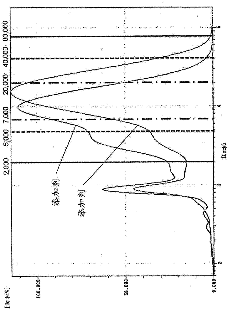
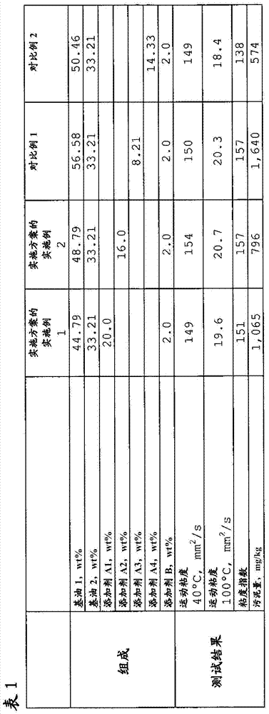
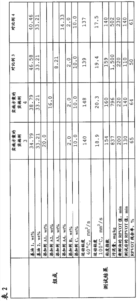
[0071] The lubricating oil composition of the present invention which has excellent extreme pressure performance (ability to prevent melting loss), generates a small amount of sludge and also has a high viscosity index will be more specifically described below by using examples and comparative examples of the embodiments, However, the present invention is not limited by these examples in any way.

[0072] The following constituent materials were used to prepare Examples and Comparative Examples of the embodiment.

[0073] 1. Base oil

[0074] Polyalphaolefin (PAO) synthetic oils are classified into Group IV according to the API (American Petroleum Institute) base oil classification.

[0075] (1-1) Base oil 1: polyalphaolefin (common name: PAO6, characterized by: kinematic viscosity at 40°C: 35.4mm 2 / s; kinematic viscosity at 100°C: 6.44mm 2 / s; viscosity index 136; density at 15°C: 0.8291g / cm 3 ; Aniline point: 130°C)

[0076] (1-2) Base oil 2: polyalphaolefin (common na...


PUM

PropertyMeasurementUnit
densityaaaaaaaaaa
densityaaaaaaaaaa
dispersityaaaaaaaaaa

Abstract

The object of this invention is to offer a lubricating oil composition which has superior extreme pressure properties (ability to prevent welding), which generates a small amount of sludge and which also has a high viscosity index. The invention provides a lubricating oil composition to which has been added a copolymer of specified olefins and alkyl methacrylates.

Description

technical field [0001] The present invention relates to lubricating oil compositions, in particular to lubricating oil compositions having excellent extreme pressure properties, generating little sludge and also having a high viscosity index. Background technique [0002] Wind energy is gaining attention as a renewable energy source for power generation. In wind power plants, speed-up gears are used to speed up the slowly turning blades so that their power can be used to turn the generator. But there are many gears in the acceleration gearbox and gear oil is needed to lubricate these gears (Gekkan Tribology, No. 273, pages 50-51, May 2010). [0003] In particular, the scale of wind power generation equipment has increased in recent years, and since it is necessary to convert a large slow driving force into a high speed by using an acceleration gearing device, the load on the gears in the gearing device has been increased, and as a result, lubrication of these gears has been...

Claims


Application Information

Patent Timeline
Patent Type & Authority Applications(China)
IPC IPC(8): C10M145/14C10M169/04C10N20/04C10N30/02C10N30/04C10N30/06C10N40/02C10N40/04C10N40/06C10N40/08C10N40/30
CPCC10M2207/283C10N2220/021C10M2205/173C10N2230/04C10M2205/02C10M2205/022C10N2240/14C10N2240/10C10N2240/06C10N2230/10C10N2230/02C10N2240/04C10N2240/08C10N2240/30C10N2230/72C10M145/14C10N2240/02C10N2220/032C10M2205/0285C10N2220/022C10N2020/04C10N2020/017C10N2020/02C10N2030/04C10N2030/02C10N2030/10C10N2030/72C10N2040/04C10N2040/06C10N2040/02C10N2040/25C10N2040/135C10N2040/08C10N2040/30C10M2209/084C10M169/04C10M161/00
Inventor 永仮光洋大塚彩乃
Owner SHELL INT RES MAATSCHAPPIJ BV
Why Eureka
Try Eureka