Beam monitor system and particle beam irradiation system
A technology of monitoring system and irradiation system, which is applied in the field of beam monitoring system of particle beam irradiation system, and can solve the problems of high cost, large-scale monitoring system, complex structure, etc.
- Summary
- Abstract
- Description
- Claims
- Application Information
AI Technical Summary
Problems solved by technology
Method used
Image

Examples
no. 1 approach
[0034] use Figure 1 to Figure 14 The first embodiment of the beam monitoring system and the particle beam irradiation system of the present invention will be described.
[0035]In the present invention, the particle beam irradiation system refers to a system for irradiating charged particle beams 12 (for example, proton beams, carbon rays, etc.) to affected parts of patients fixed on a treatment table (bed device) 10 in a treatment room.
[0036] First, use Figure 1 ~ Figure 4 The configuration of the particle beam irradiation system of the present invention will be described.
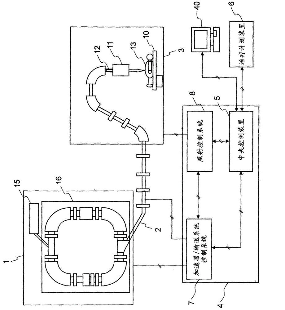
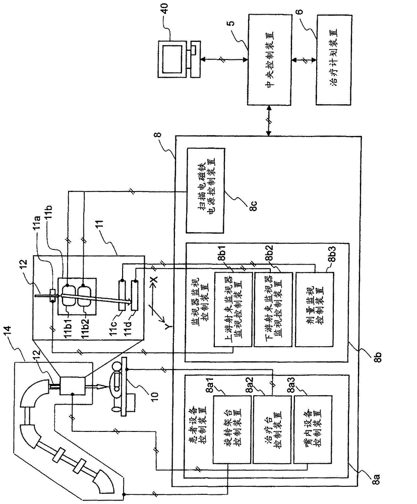
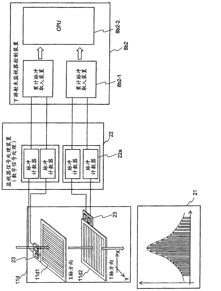
[0037] figure 1 is a configuration diagram showing the overall configuration of the first embodiment of the particle beam irradiation system of the present invention, figure 2 It is a configuration diagram showing the outline of a scanning irradiation system and an irradiation control system constituting the first embodiment of the particle beam irradiation system of the present invention, imag...
no. 2 approach
[0158] use Figure 15 and Figure 16 A second embodiment of the beam monitoring system and particle beam irradiation system of the present invention will be described.
[0159] Figure 15 It is a figure which shows an example of the distribution of the fitting function and the measured value of the 2nd embodiment of the beam monitoring system of this invention, Figure 16 It is a diagram showing another example of the distribution of the fitting function and the actual measurement value of the second embodiment of the beam monitoring system of the present invention.
[0160] In the beam monitoring system of the second embodiment, in the upstream beam monitor monitoring and control device 8b1 or the downstream beam monitor monitoring and control device 8b2, as conditions for judging appropriate irradiation, in addition to beam position and beam width The condition that the calculation result is less than the allowable value is also applied when the average value (variance va...
no. 3 approach
[0180] use Figure 17 A third embodiment of the beam monitoring system and particle beam irradiation system of the present invention will be described.
[0181] Figure 17 It is a flowchart of the control of charged particle beam irradiation by raster scanning method.
[0182] The first embodiment is a particle beam irradiation system including a beam monitoring system for monitoring the beam position and beam width in the spot scanning irradiation method. Beam monitoring system that monitors beam position and beam width.
[0183] The particle beam irradiation system according to the present embodiment includes the following beam monitoring system for monitoring the beam position and beam width in the raster scanning irradiation method, which divides the affected part of the patient 13 into a plurality of layers in the beam advancing direction, and Irradiation of the charged particle beam is maintained continuously in each layer (beam is kept on), and the charged particle b...
PUM
 Abstract
Description
Claims
Application Information
 - R&D
- Intellectual Property
- Life Sciences
- Materials
- Tech Scout
- Unparalleled Data Quality
- Higher Quality Content
- 60% Fewer Hallucinations
Browse by: Latest US Patents, China's latest patents, Technical Efficacy Thesaurus, Application Domain, Technology Topic, Popular Technical Reports.
© 2025 PatSnap. All rights reserved.Legal|Privacy policy|Modern Slavery Act Transparency Statement|Sitemap|About US| Contact US: help@patsnap.com