Automatic centrifuge rotor state recognition system

An automatic identification system and centrifuge rotor technology, applied in the direction of centrifuges, etc., can solve the problems of affecting the centrifuge, cracking, even breaking into several pieces, smashing into the inner cavity, and twisting of the centrifuge body, so as to improve safety Effect

Active Publication Date: 2015-02-11
SHANGHAI ANTING SCI INSTR FACTORY
View PDF6 Cites 3 Cited by
  • Summary
  • Abstract
  • Description
  • Claims
  • Application Information

AI Technical Summary

Problems solved by technology

Now most centrifuges do not have a rotor identification system. If the set speed exceeds its maximum speed or runs at a higher speed in its critical speed range, it will affect the overall performance of the centrifuge. If there is a rotor material defect, it is damaged during use Corrosion, rotor defects due to exceeding the service life of the rotor, shaft defects and other reasons will cause unexpected failures and dangers. In serious cases, major accidents will occur, and some will cause the rotor to crack or even break into several pieces, smashing into the inner cavity The body of the centrifuge will be twisted and the mechanism will be damaged. In severe cases, the debris will knock open the cover door and escape at high speed. The more rotors there are, the greater the danger. The ultracentrifuge with a speed of more than 30,000rpm is more dangerous. If the rotor identification technology can be used, it can avoid the wrong setting of the maximum speed of the rotor, make it run within the maximum speed range, prevent the rotor from exceeding its maximum speed, and make statistics on the operation of the rotor and the running speed of the whole machine. Avoid personal injury and property damage to operators and laboratory equipment to the greatest extent

Method used


Image

  • Automatic centrifuge rotor state recognition system
  • Automatic centrifuge rotor state recognition system
  • Automatic centrifuge rotor state recognition system

Examples


Embodiment Construction

[0025] The present invention will be described in detail below in conjunction with the accompanying drawings and specific embodiments. This embodiment is carried out on the premise of the technical solution of the present invention, and detailed implementation and specific operation process are given, but the protection scope of the present invention is not limited to the following embodiments.

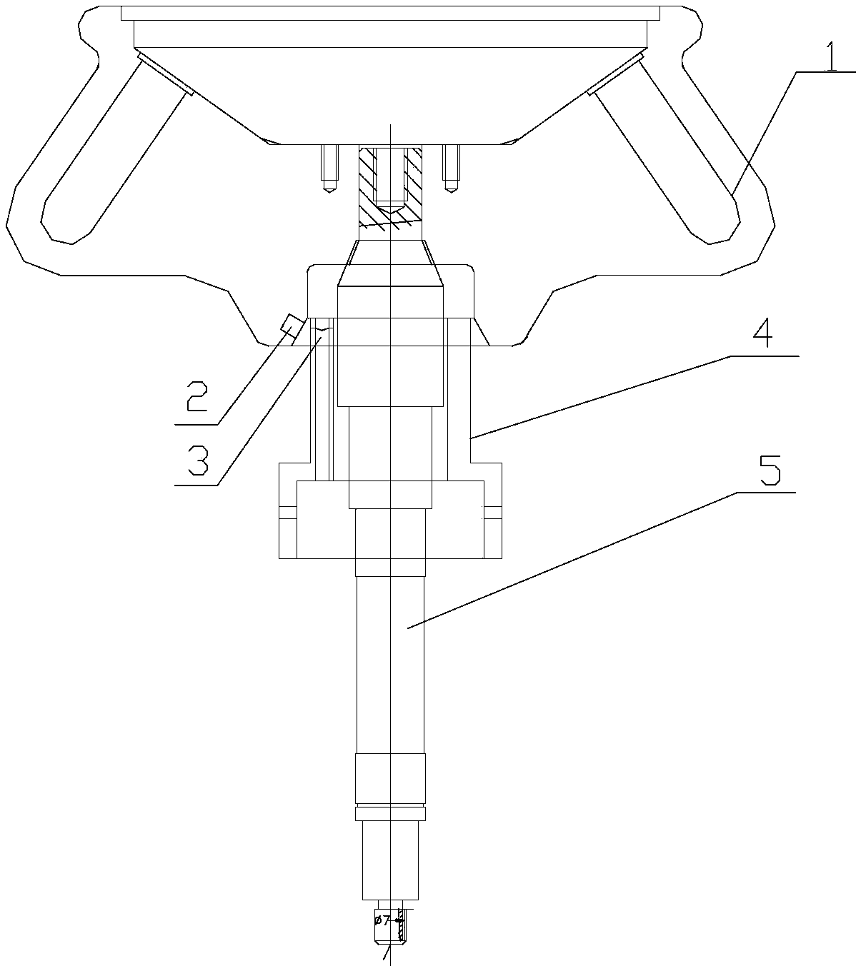
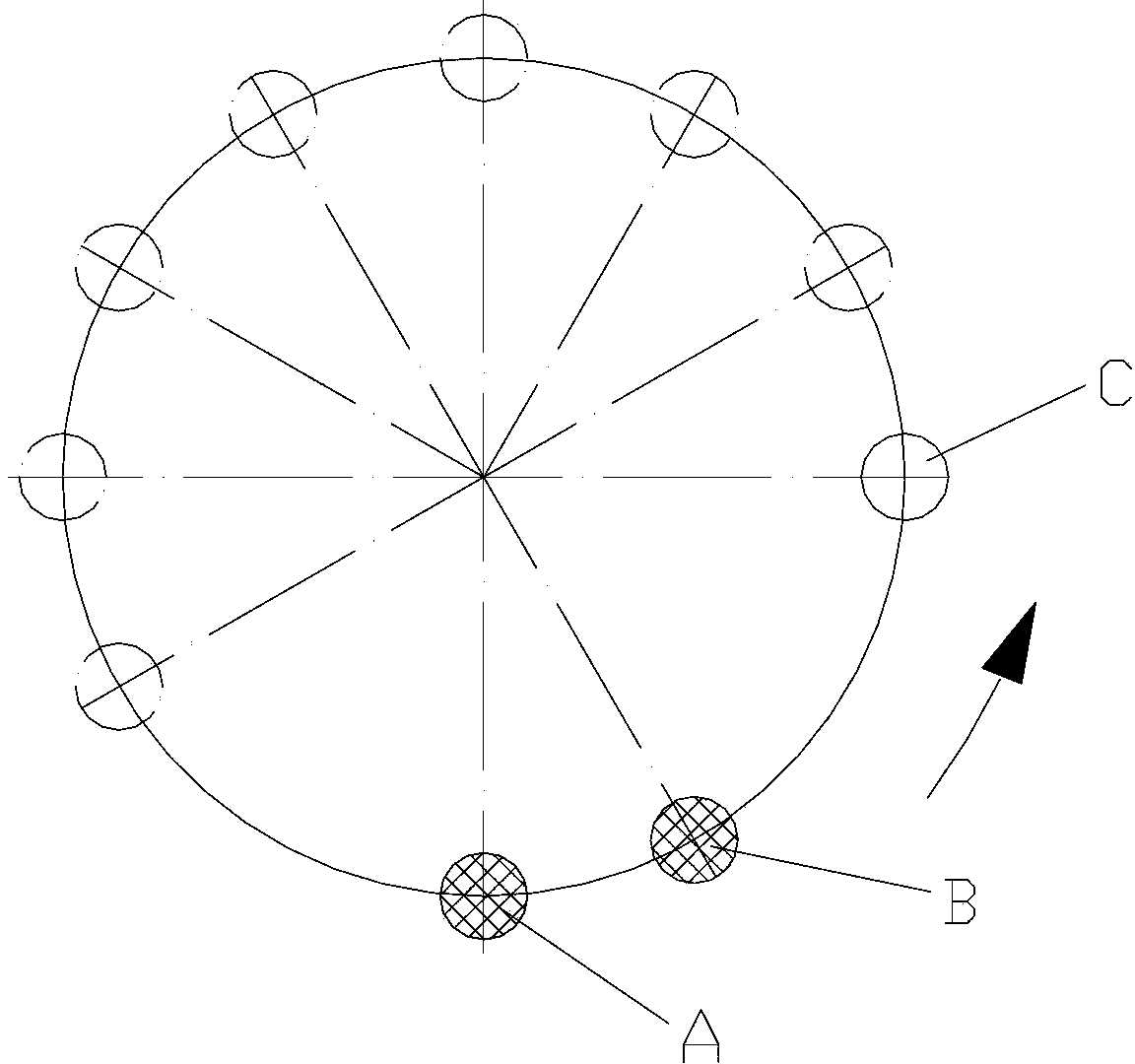
[0026] like figure 1 As shown, a centrifuge rotor state automatic recognition system includes a single-chip microcomputer, a Hall sensor 3, a sensor bracket 4, a magnetic steel assembly 2 and an alarm assembly, and the single-chip microcomputer is respectively connected to the Hall sensor 3 and the alarm assembly. The magnetic steel assembly 2 is fixed on the bottom of the rotor 1 and rotates with the rotor 1. The sensor bracket 4 is set under the rotor 1, and the Hall sensor 3 is set on the sensor bracket 4; the rotor 1 drives the magnetic steel assembly 2 at a low speed. Rotate, th...


PUM


Abstract

The invention relates to an automatic centrifuge rotor state recognition system which comprises a single chip microcomputer, an Hall sensor, a sensor bracket, a magnetic steel component and an alarm component, wherein the single chip microcomputer is connected with each of the Hall sensor and the alarm component; the magnetic steel component is fixed at the bottom of the rotor and rotates along with the rotor; the sensor bracket is arranged below the rotor; the Hall sensor is arranged on the sensor bracket; the rotor drives the magnetic steel component to rotate; the Hall sensor emits high/low level signals according to the magnetic steel component and transmits the high/low level signals to the single chip microcomputer; the single chip microcomputer is used for recognizing the rotor according to the received signals and used for transmitting alarm signals to the alarm component according to the recognition result; the alarm component is used for making alarm according to the alarm signals. Compared with the prior art, the automatic centrifuge rotor state recognition system can recognize the rotor, so that the security of the whole machine is improved, and besides, an operator can master the expected service life of the rotor, and thus the rotor can be replaced or continuously used.

Description

technical field [0001] The invention relates to a rotor operation monitoring device, in particular to a centrifuge rotor state automatic identification system. Background technique [0002] The rotor is the core component of the centrifuge. A multi-functional centrifuge can usually be equipped with multiple rotors. Different types of rotors are used to meet different needs to achieve its "multi-function". The common rotors can be divided into horizontal and horizontal according to their structures. Rotors and fixed angle rotors, in addition to continuous flow rotors, zonal rotors, elutriation rotors, vertical rotors, etc. The material of the fixed-angle rotor is generally quenched and tempered LY12, LC4 or carbon fiber; the common material of the horizontal rotor is cast aluminum or cast stainless steel, and its composition can also be adjusted according to strength or other requirements. The rotor not only directly affects the separation effect, it is also the main force-b...

Claims


Application Information

Patent Timeline
Patent Type & Authority Applications(China)
IPC IPC(8): B04B15/00
Inventor 陈丽华
Owner SHANGHAI ANTING SCI INSTR FACTORY
Why Eureka
Try Eureka