Method for constructing a driver's cab of a commercial vehicle

A technology for cabs and commercial vehicles, applied in the field of cabs, can solve problems such as unergonomic and time-consuming, and achieve the effect of improving pre-grouping, efficient and flexible assembly

Active Publication Date: 2015-02-11
MAN NUTZFAHRZEUGE AG
View PDF7 Cites 6 Cited by
  • Summary
  • Abstract
  • Description
  • Claims
  • Application Information

AI Technical Summary

Problems solved by technology

However, this method also has the disadvantage of time-consuming and unergonomic work in the interior and lower part of the cab for assembling the interior

Method used


Image

  • Method for constructing a driver's cab of a commercial vehicle
  • Method for constructing a driver's cab of a commercial vehicle
  • Method for constructing a driver's cab of a commercial vehicle

Examples


Embodiment Construction

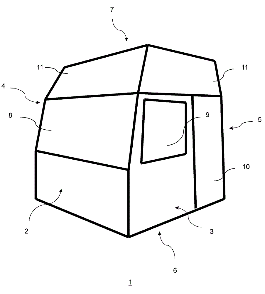
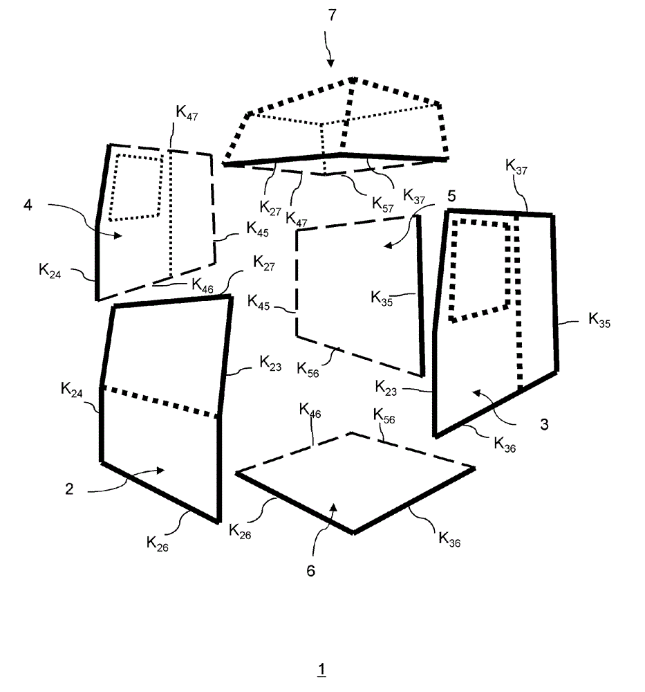
[0032] figure 1 and figure 2 A schematic perspective view of a modularly constructed driver's cab 1 is shown. and figure 1 Instead, in figure 2 Also shows edges that are not visible in the selected perspective as dashed lines.

[0033] The driver's cab 1 shown is composed of a front wall 2 , two opposite side walls 3 , 4 , a rear wall 5 , a roof module 7 and a floor part 6 . The individual wall modules 2 to 7 are connected together and generally consist of steel sheets. The side walls 3 , 4 have cutouts 8 to 10 for the windshield, side windows and driver's door. A profiled roof structure 7 adjoins the side walls 3 , 4 and the front and rear walls 2 , 5 .

[0034] exist image 3 In , the edges adjoining or connecting the respective adjacent side walls 3, 4 are highlighted. exist image 3 In , the visible connection edges are indicated by thick solid lines, while in image 3 Connection edges that are not visible in the perspective view of are indicated by dashed line...


PUM


Abstract

The invention relates to a method for constructing a driver's cab (1) of a commercial vehicle. The method comprises the steps of: providing individual walls (2-7) of the cab (1) comprising a front wall (2), side walls (3, 4), a rear wall (5 ), a bottom (6) and a roof (7); painting the provided individual walls (2-7); equipping at least one single painted wall (2 to 7) with an equipment element; and joining the single painted walls (2 to 7) to the commercial vehicle cab (1).

Description

technical field [0001] The invention relates to a method for assembling a driver's cab of a commercial vehicle, such as a truck. Background technique [0002] The cockpit of a truck consists of a floor or bottom assembly, a roof, side walls, and front and rear walls. For the sake of stability, these walls can also be designed as a double-layer structure consisting of inner and outer plates. In the method known from the prior art, the above-mentioned wall components of the driver's cab are welded as profiled panels within the body-in-white to form the driver's cab. In this case, individual components such as system brackets or roofs can also be mounted on the rest of the driver's cab only in the pregrouped state on the assembly line. [0003] Subsequent body-in-white - polishing, surface treatment, painting and assembly are all done on the cab, under the cab or inside. In this case, especially the work under and inside the driver's cab is labor-intensive and equipment-tech...

Claims


Application Information

Patent Timeline
Patent Type & Authority Applications(China)
IPC IPC(8): B62D33/06B62D65/04
CPCB62D33/06B62D65/02B62D65/04
Inventor S.舍尔
Owner MAN NUTZFAHRZEUGE AG
Why Eureka
Try Eureka