
Electromagnetic oil sprayer

A technology of electromagnetic and solenoid valves, applied in the direction of machines/engines, fuel injection devices, engine components, etc., can solve problems such as high cracks, hardening of the outer surface, and the influence of the distribution of magnetic force lines

Active Publication Date: 2015-02-11
ROBERT BOSCH GMBH
View PDF4 Cites 0 Cited by
  • Summary
  • Abstract
  • Description
  • Claims
  • Application Information

AI Technical Summary

Problems solved by technology

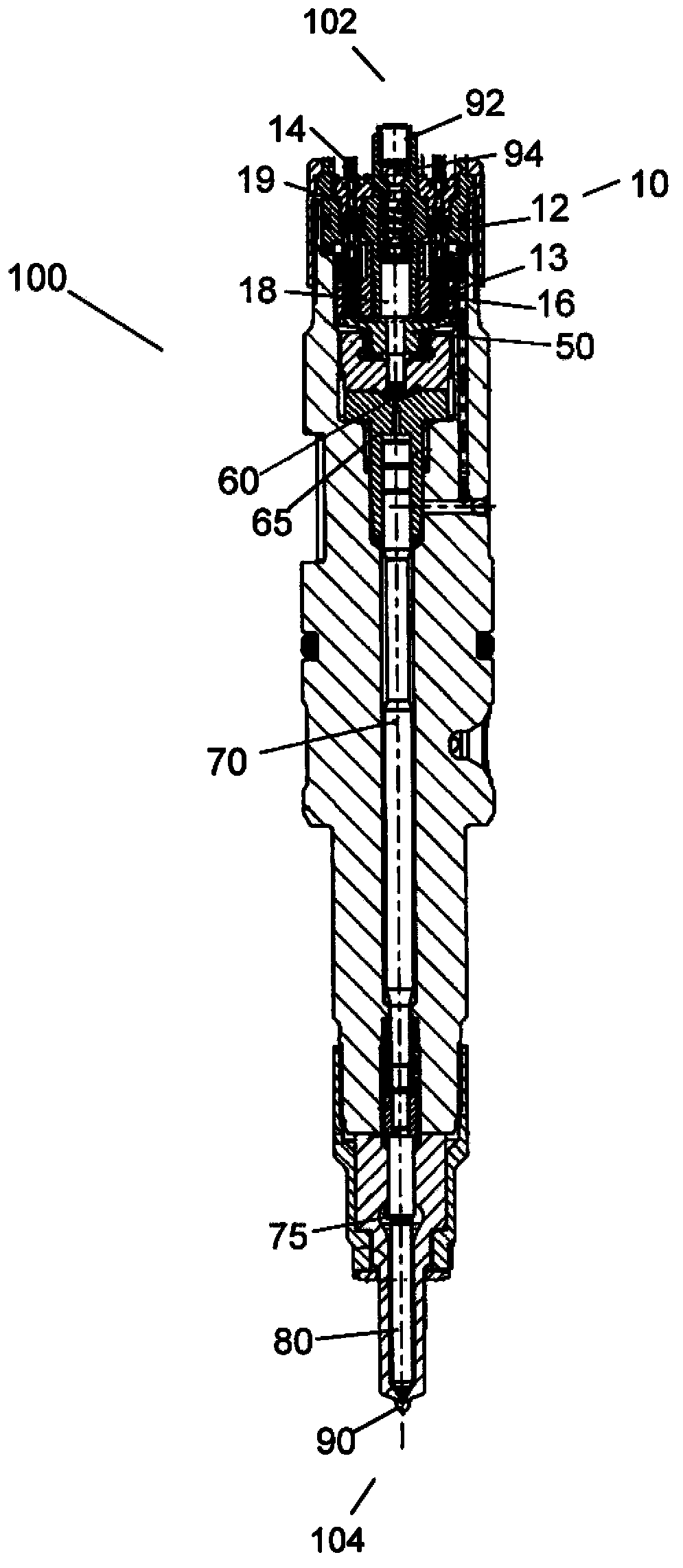
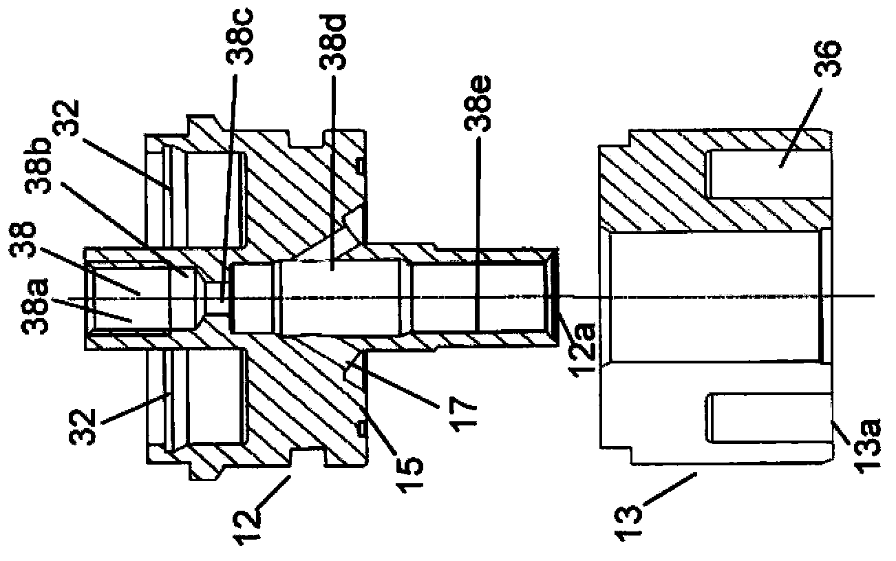
However, the carbonization process hardens all the outer surfaces of the electromagnetic housing 12, so that the subsequent welding process is adversely affected, there is a high risk of cracking on the inner surface of the first part 38a, and moreover, the distribution of the magnetic field lines is also affected

Method used


Image

  • Electromagnetic oil sprayer
  • Electromagnetic oil sprayer
  • Electromagnetic oil sprayer

Examples


Embodiment Construction

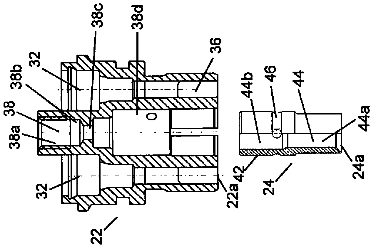
[0036] The inventive point of the present invention lies in the improved structure of the solenoid valve control assembly of the electromagnetic fuel injector, which meets the requirements of making the magnetic core relatively soft and making the inner surface of the guide armature shaft wear-resistant.

[0037] According to one aspect of the present invention, in the electromagnetic valve control assembly of the electromagnetic fuel injector, the magnetic core, that is, the part accommodating the electromagnetic coil in the prior art, is formed as one part with the electromagnetic housing. The electromagnetic housing according to the invention differs from prior art electromagnetic housings that accommodate a movable member and a return spring. The electromagnetic housing according to the invention is made of a relatively soft metal material, for example, a steel material with a hardness below 400 HV10, which may be unhardened or only slightly hardened steel material. This s...


PUM

PropertyMeasurementUnit
Hardnessaaaaaaaaaa
Hardnessaaaaaaaaaa

Abstract

The invention discloses an electromagnetic oil sprayer comprising an electromagnetic housing and a sleeve member which are made of different materials, an electromagnetic coil, a movable component, a return spring and a connector pin. The rigidity of the sleeve member is higher than that of the electromagnetic housing, and the sleeve member is installed into the electromagnetic housing coaxially; the electromagnetic coil is accommodated by the wall of the electromagnetic housing; the movable component and the return spring are accommodated in the internal space limited by the inter surface of the sleeve member; the partial connector pin is embedded into the wall of the electromagnetic housing, and the connector pin is electrically connected to the electromagnetic coil. When the electromagnetic coil is powered on, the movable component moves in a first direction opposite to the effect of the return spring under the magnetic force produced by the electromagnetic coil; when the electromagnetic coil is powered off, the movable component moves in a second direction opposite to the first direction under the effect of the return spring. The invention further relates to an electromagnetic oil sprayer including an electromagnetic valve control component.

Description

technical field [0001] The invention relates to an electromagnetic fuel injector, in particular to a solenoid valve control assembly of the electromagnetic fuel injector. Solenoid injectors are used in common rail injection systems of internal combustion engines such as diesel engines. Background technique [0002] Electromagnetic injectors are used to inject high-pressure fuel into the combustion chamber of internal combustion engines, and are widely used in common rail injection systems due to their precise control and high-speed response to fuel injection. [0003] figure 1 is a longitudinal sectional view of a conventional electromagnetic injector 100 in the prior art. [0004] The solenoid injector 100 includes a solenoid valve control assembly 10 at a first end 102 thereof for controlling a needle at a second end 104 of the solenoid injector 100 via an armature 50, a control chamber 65 and a needle control piston 70. The opening and closing of valve 80. By controll...

Claims


Application Information

Patent Timeline
IPC IPC(8): F02M61/16
Inventor 袁森琦S·克劳斯杜云芝
Owner ROBERT BOSCH GMBH
Learn More