Thermocompressor

A technology of injectors and steam nozzles, applied in jet pumps, machines/engines, non-displacement pumps, etc., can solve problems such as inability to obtain pump efficiency

Inactive Publication Date: 2015-02-11
SASAKURA ENG CO LTD
View PDF6 Cites 10 Cited by
  • Summary
  • Abstract
  • Description
  • Claims
  • Application Information

AI Technical Summary

Problems solved by technology

Sufficient pump efficiency cannot be obtained with this structure, and the invention of Patent Document 1 proposes that the inner diameter d1 of the mixing tube 51 be 2.5 to 4.0 times the injection diameter d2 of the steam nozzle 52

Method used


Image

  • Thermocompressor
  • Thermocompressor
  • Thermocompressor

Examples


Embodiment Construction

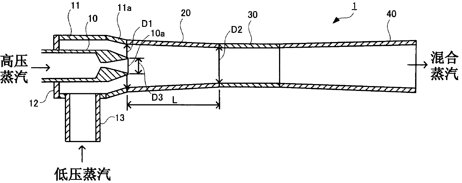
[0032] Hereinafter, one embodiment of the present invention will be described with reference to the drawings. figure 1 It is a schematic configuration diagram of a steam ejector according to an embodiment of the present invention. Such as figure 1 As shown, the steam ejector 1 is constituted by sequentially connecting a support member 11 , a mixing chamber 20 , a throat member 30 and a diffuser 40 .

[0033] The support member 11 is formed in a cylindrical shape, one end thereof is closed by an end plate 12 , and the other end thereof is connected to one end of the mixing chamber 20 . Inside the support member 11 , the tip portion of the steam nozzle 10 injecting high-pressure steam extends through the center of the end plate 12 . An injection port 10 a is formed at the tip of the steam nozzle 10 . The steam nozzle 10 is fixed to the end plate 12 so that one end surface of the mixing chamber 20 and the injection port 10 a are substantially on the same plane. An introduct...


PUM


Abstract

The present invention provides a thermocompressor capable of improving exhaust pressure of mixed steam of drive steam and intake steam. The thermocompressor comprises: a steam nozzle (10) ejecting high pressure steam from an ejection opening (10a) formed at the front end; a mixing chamber (20) formed to be cylinder-shaped with two ends open and configured with the ejection opening (10a) at one end; and a diffuser (40) connected with the other end side of the mixing chamber (20). The high pressure steam is ejected from the ejection opening (10a), low pressure steam is attracted in the mixing chamber (20) from the periphery of the ejection opening (10a), pressure of the mixed steam is raised in the diffuser (40), and then the mixed steam is exhausted to the outside. The inner diameter of the mixing chamber (20) is reduced from one end to the other end, and the ratio (D1 / D2) of the inner diameter (D1) of one end and the inner diameter (D2) is in a range of 1.1-1.3.

Description

technical field [0001] The present invention relates to steam injectors (thermocompressors). Background technique [0002] The steam injector is constructed in such a way that the high-pressure steam is used as the driving fluid, the low-pressure steam is sucked into the mixing chamber for mixing, and the pressure of the mixed steam is raised by a diffuser before being discharged. As a structure for sucking mixed fluid using high-pressure driving steam, there is a steam jet pump disclosed in Patent Document 1, for example. [0003] In Patent Document 1, a method including Figure 4 Shown is a mixing tube 51 , a steam nozzle 52 and a steam jet pump 50 of a liquid discharge nozzle 53 . The steam injection pump 50 injects high-pressure steam from the steam nozzle 52 , whereby the liquid to be transported flows into the mixing tube 51 from the liquid inlet 54 , and is sent to the liquid discharge nozzle 53 at an increased flow rate in the tapered mixing tube 51 . Then, the liq...

Claims


Application Information

Patent Timeline
Patent Type & Authority Applications(China)
IPC IPC(8): F04F5/24
CPCF04F5/16F04F5/44F04F5/46
Inventor 水谷淳二有本光希秦野善行
Owner SASAKURA ENG CO LTD
Why Eureka
Try Eureka