Pipe socket forming method

A forming method and pipeline technology, which is applied in the direction of pipeline connection arrangement, pipe/pipe joint/pipe fitting, mechanical equipment, etc., can solve the problem of poor connection quality between pipe socket and pipe socket, complicated production process, and difficulty in inserting pipe socket into pipe socket In order to achieve the effect of convenient and adjustable layout path, smooth and unobstructed cooperation, and smooth and flat inner surface

Active Publication Date: 2016-12-07
GOODY SCI & TECH CO LTD
View PDF8 Cites 0 Cited by
  • Summary
  • Abstract
  • Description
  • Claims
  • Application Information

AI Technical Summary

Problems solved by technology

Although the resistance wire arranged by this method can meet the requirements of use to a certain extent, the resistance wire is mechanically fixed in the inner hole of the pipe socket. On the one hand, it will make it difficult for the pipe socket to be inserted into the pipe socket during installation and construction; on the other hand On the one hand, even if the pipe socket is barely inserted into the pipe socket, there is still the problem that the pipe socket and the pipe socket are not tightly matched, which leads to poor connection quality between the pipe socket and the pipe socket
In addition, the existing resistance wire wiring method of forming the pipe socket first and then arranging the resistance wire still has the defects of complex production process, low degree of automation, and heavy dependence on the proficiency of workers

Method used


Image

  • Pipe socket forming method
  • Pipe socket forming method

Examples


Embodiment Construction

[0030] The present invention will be further described below in conjunction with the accompanying drawings and specific embodiments, so that those skilled in the art can better understand the present invention and implement it, but the examples given are not intended to limit the present invention.

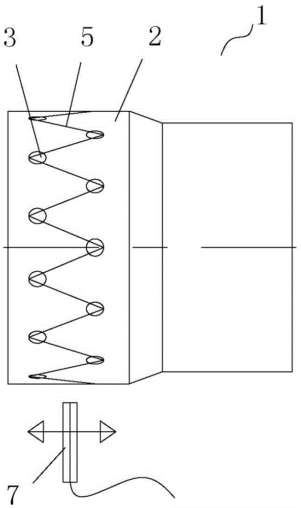
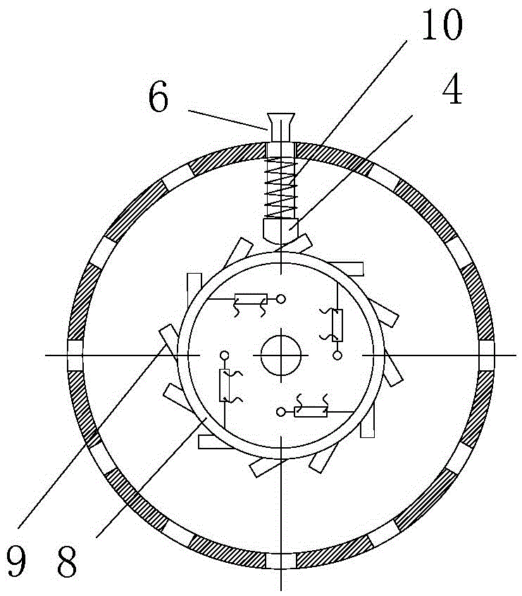
[0031] Such as figure 1 As shown, it is a structural schematic diagram of the electric resistance wire wiring device adopted in the pipe socket forming method of the present invention. The electrical fusion resistance wire wiring device of this embodiment includes a molding die 1, a resistance wire arrangement section 2 is provided on the forming mold 1 corresponding to the resistance wire arrangement area of ​​the pipeline, and the resistance wire arrangement section 2 is arranged according to a preset resistance wire arrangement path A limiting hole 3 is provided, and each limiting hole 3 is provided with a radially movable anchor column 4 , and the top of the anchor column 4 is...


PUM


Abstract

The invention discloses a pipeline socket forming method. The method comprises the following steps: (1) wiring: arranging a resistance wire on the peripheral wall of a forming mould according to a preset arrangement path; (2) forming: forming a pipeline socket on the forming mould on which the resistance wire is arranged; (3) mould unloading. The pipeline socket forming method adopts process steps of wiring and then forming the pipeline socket. Compared with the traditional process steps of forming the pipeline socket and then wiring, the pipeline socket forming method has the advantages that 1, the resistance wire is arranged in advance, so that the arrangement path of the resistance wire is convenient and adjustable; 2, in the forming process of the pipeline socket, the resistance wire is directly buried in a plastic layer of the pipeline socket and is flush with the inner surface of the plastic layer, and the inner surface of the pipeline socket is smooth and flat and can be matched with a pipeline insertion opening well.

Description

technical field [0001] The invention belongs to the technical field of pipeline connection, in particular to a method for forming a pipeline socket. Background technique [0002] The Chinese patent application with the publication number CN 103672276A discloses a pipe hot-melt wiring method, which includes the following steps: in the area where the plastic pipe needs to be welded, use a wiring knife to inlay metal wires at both ends of the plastic pipe according to the corresponding wiring pitch The plastic surface of the outer diameter or inner diameter is covered with the area to be welded. A section of the two ends of the metal wire is reserved to be exposed outside the plastic surface. After the metal wire is laid, it is welded. After the welding is completed, the The metal wire ends exposed outside the plastic surface layer of the plastic pipe are cut off. [0003] That is, when the existing pipe socket is processed, the pipe socket is formed first, and then the resist...

Claims


Application Information

Patent Timeline
Patent Type & Authority Patents(China)
IPC IPC(8): F16L47/03
CPCF16L47/03
Inventor 田从陆李贤梅付志敏覃海波
Owner GOODY SCI & TECH CO LTD
Why Eureka
Try Eureka