
Method and apparatus for sending synchronizing signal and method and apparatus for determining carrier type

A synchronization signal and carrier type technology, which is applied in the field of determining the carrier type and sending synchronization signals, and can solve problems such as simultaneous transmission, adding carrier type indication signaling, and transmitting PSS

Active Publication Date: 2015-02-11
CHINA MOBILE COMM GRP CO LTD
View PDF2 Cites 60 Cited by
  • Summary
  • Abstract
  • Description
  • Claims
  • Application Information

AI Technical Summary

Problems solved by technology

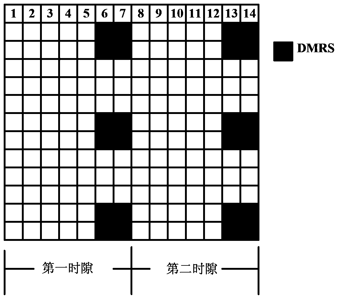
[0009] The embodiment of the present invention provides a method and device for sending a synchronization signal and determining a carrier type, which is used to solve the problem in the prior art that the configured 4th / or 5th The problem of transmitting PSS with one symbol, and at the same time, reference signals such as TRS / DMRS and PSS / SSS cannot be transmitted at the same time, which reduces the synchronization tracking accuracy, and the problem of adding additional carrier type indication signaling

Method used


Image

  • Method and apparatus for sending synchronizing signal and method and apparatus for determining carrier type
  • Method and apparatus for sending synchronizing signal and method and apparatus for determining carrier type
  • Method and apparatus for sending synchronizing signal and method and apparatus for determining carrier type

Examples


Embodiment 1

[0091] Such as image 3 As shown, it is a schematic flowchart of a method for sending a synchronization signal according to Embodiment 1 of the present invention, and the method includes:

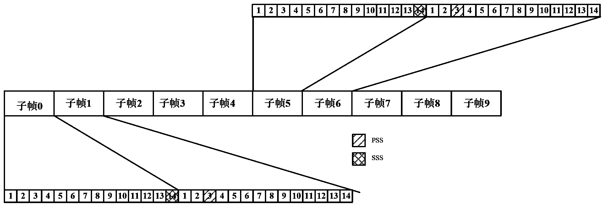
[0092] Step 101: According to the pre-configured positional relationship between the time domain position for sending the primary synchronization signal PSS and the time domain position for sending the secondary synchronization signal SSS, select the time domain position for sending The time domain position of the primary synchronization signal PSS, and the time domain position for sending the secondary synchronization signal SSS.

[0093] Wherein, the preconfigured positional relationship between the time domain position for sending the primary synchronization signal PSS and the time domain position for sending the secondary synchronization signal SSS satisfies: neither adjacent nor separated by 2 OFDM OFDM symbols.

[0094]In step 101, it is assumed that possible reference signals inclu...

Embodiment 2

[0130] Such as Figure 7 As shown, it is a schematic flowchart of a method for determining a carrier type according to Embodiment 2 of the present invention. Embodiment 2 of the present invention is an invention under the same inventive concept as Embodiment 1 of the present invention, and the method includes:

[0131] Step 201: Receive a synchronization signal sent by a synchronization source base station.

[0132] Wherein, the synchronization signal includes a primary synchronization signal PSS and a secondary synchronization signal SSS.

[0133] Step 202: Determine the time domain position used by the synchronization source base station for sending the PSS, and determine the time domain position used by the synchronization source base station for sending the SSS.

[0134] Specifically, in step 202, when it is determined that the time domain position used by the synchronization source base station for sending the synchronization signal is sent through the time domain posit...

Embodiment 3

[0154] Such as Figure 8 As shown, it is a schematic structural diagram of a device for sending a synchronization signal in Embodiment 3 of the present invention. Embodiment 3 of the present invention is an invention under the same inventive concept as Embodiment 1 to Embodiment 2 of the present invention. The device Including: a time domain position determination module 11 and a sending module 12, wherein:

[0155] The time-domain position determining module 11 is configured to, according to the pre-configured positional relationship between the time-domain position for sending the primary synchronization signal PSS and the time-domain position for sending the secondary synchronization signal SSS, from a time-domain position not yet occupied by all reference signals , select the time domain position for sending the primary synchronization signal PSS, and the time domain position for sending the secondary synchronization signal SSS, wherein the preconfigured time domain positi...


PUM


Abstract

The present invention discloses a method and apparatus for sending a synchronizing signal and a method and apparatus for determining a carrier type. The method for sending a synchronizing signal includes: according to a preset position relation between a time domain position used for sending a PSS and a time domain position used for sending an SSS, selecting a time domain position for sending the PSS and a time domain position for sending the SSS from the time domain positions which are not occupied by all reference signals yet, wherein, the position relation meets a condition that the time domain position used for sending the PSS and the time domain position used for sending the SSS are not adjacent or spaced apart by two ODFM symbols; using the selected time domain position of the PSS to send the PSS, and using the selected time domain position of the SSS to send the SSS, which can avoid conflicting with resource positions used for sending reference signals such as TRS / DMRS, and increase accuracy of synchronous tracking; moreover, the method is adapted for configuring a short DwPTS system, and also impliedly indicates the carrier type, thereby reducing signaling overheads of the system and saving the system resource.

Description

technical field [0001] The invention relates to the field of wireless communication, in particular to a method and equipment for sending synchronization signals and determining carrier types. Background technique [0002] In the R11 protocol of the LTE (Long Term Evolution, long-term evolution) system and previous protocol versions, the synchronization signal is used for cell search and initial clock synchronization between base stations. Wherein, the synchronization signal is divided into PSS (Primary Synchronization Signal, primary synchronization signal) and SSS (Secondary Synchronization Signal, secondary synchronization signal). In different system standards, resource location information for sending the PSS / SSS is different (that is, the location in the frequency domain is the same, but the location in the time domain is different). [0003] For example: Assuming a conventional CP (Cyclic Prefix, cyclic prefix) (a conventional CP contains 14 OFDM symbols) as an exampl...

Claims


Application Information

Patent Timeline
IPC IPC(8): H04W72/04H04W56/00H04L27/26
Inventor 王锐沈晓冬刘建军
Owner CHINA MOBILE COMM GRP CO LTD
Learn More