

Stirrer
A technology of stirrer and stirring plate, which is applied in the direction of mixers with rotating stirring devices, chemical instruments and methods, dissolution, etc., can solve the problems of long stirring time, reduced stirring effect, and failure to achieve stirring, etc., to achieve increased stirring The effect of increasing the number of times, stirring efficiency, and improving the stirring effect
- Summary
- Abstract
- Description
- Claims
- Application Information
AI Technical Summary
Problems solved by technology
Method used
Image

Examples
Embodiment 1
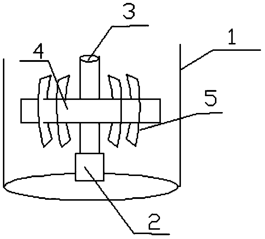
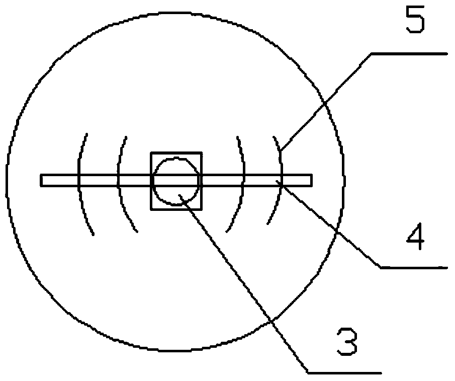
[0036] Such as figure 1 , 2 As shown, a stirrer includes a housing 1, a motor 2 installed at the center of the bottom of the housing 1, a stirring shaft 3 vertically installed above the motor 2, and a stirring beam 4 vertically fixed to the stirring shaft 3; it also includes an arc-shaped stirring Plate 5; two arc-shaped stirring plates 5 are respectively arranged on both sides of the stirring shaft 3, and the arc-shaped stirring plates are fixed on the stirring beam; the distance between the bottom end of the arc-shaped stirring plate and the bottom of the housing 1 is 5 mm; the stirring plate The two ends of the stirring beam are vertically fixed; the stirring plate is arc-shaped and relatively symmetrically arranged at the two ends of the stirring beam. The stirring beam passes through the center of the arc-shaped stirring plate, and a stirring member is added. Stirring plate 5 stirs at the same time, which increases the number of stirring times and improves the stirring e...
Embodiment 2
[0038] Referring to Example 1, further, the agitator includes a housing 1, a motor 2 installed at the center of the bottom of the housing 1, a stirring shaft 3 vertically installed above the motor 2, and a stirring beam 4 vertically fixed to the stirring shaft 3 ; It also includes an arc-shaped stirring plate 5; there are 4 arc-shaped stirring plates at one end of the beam, and they are arranged in the same arc direction.
Embodiment 3
[0040] Further, the agitator includes a housing 1, a motor 2 installed at the center of the bottom of the housing 1, a stirring shaft 3 vertically installed above the motor 2, and a stirring beam 4 vertically fixed to the stirring shaft 3; it also includes an arc Stirring plate 5; the arc-shaped stirring plate is viewed from the outside of the stirring shaft, and the cross-sectional shapes are respectively 1 / 6 arc, 1 / 5 arc, and 1 / 4 arc.
PUM
 Abstract
Description
Claims
Application Information