Fully automatic interweaving method for reinforcing bar nets of underground continuous wall

An underground continuous wall and steel mesh technology, applied in the field of construction machinery, can solve the problems of large volume of steel cages, unsafe, non-continuous foundation walls, etc., and achieve the effect of reducing the amount of labor and improving efficiency.

Active Publication Date: 2015-02-18
GEOTECHN TECH
View PDF5 Cites 4 Cited by
  • Summary
  • Abstract
  • Description
  • Claims
  • Application Information

AI Technical Summary

Problems solved by technology

At present, on construction sites, drilling machines are generally used to form pile holes in the foundation soil. Workers weave steel cages, put the steel cages into the pile holes, and then pour concrete building foundations into them. There are complicated steps, low efficiency, and manpower consumption. In addition, the established foundation wall is not continuous, and its strength is low; the existing underground continuous wall is generally first excavated by various digging machines to guide wall grooves in the ground, and then the steel cage is manually welded, and the crane is used to move the wall The steel cage is placed vertically into the guide wall groove, and finally the concrete is poured into it. The steps are complicated and the efficiency is low. Moreover, the steel cage is large in size, so it is difficult to lift and put it into the guide wall groove; the existing operation method requires manual climbing. It is unsafe to work in the soil tank below the ground
At present, there is no design concept that integrates underground automatic trenching and automatic weaving of steel mesh, and there is no machine that can realize this design concept.

Method used


Image

  • Fully automatic interweaving method for reinforcing bar nets of underground continuous wall
  • Fully automatic interweaving method for reinforcing bar nets of underground continuous wall
  • Fully automatic interweaving method for reinforcing bar nets of underground continuous wall

Examples


Embodiment Construction

[0033] The present invention will be further described below in conjunction with the accompanying drawings and embodiments.

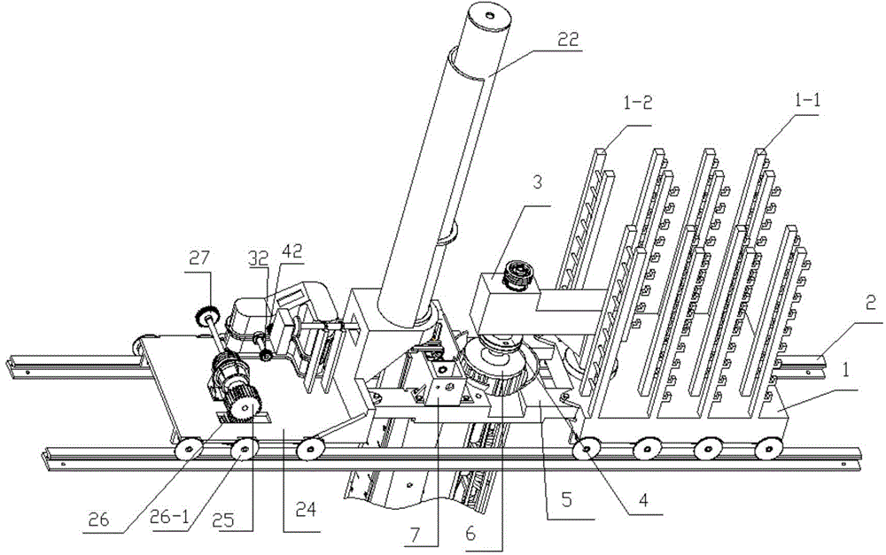
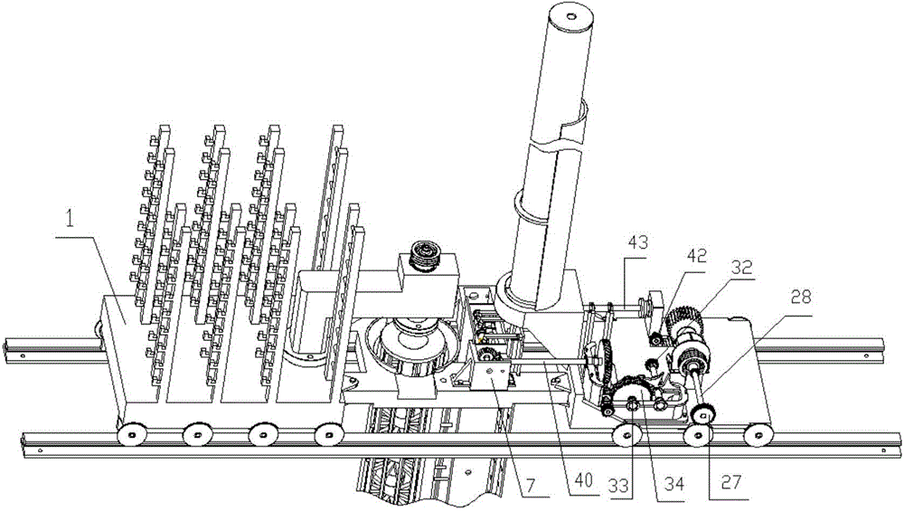
[0034] Such as figure 1 and 2 As shown, a method for fully automatic interweaving of steel mesh for underground diaphragm walls, the specific steps are as follows:

[0035] Step 1: Put steel bars into the longitudinal steel bar conveying mechanism, and connect the high-pressure water pipe to the high-pressure water input hole of the groove milling mechanism.

[0036] Step 2: The driving mechanism drives the groove milling bit of the groove milling mechanism to dig out the initial groove section of the continuous wall guide wall groove. When the groove milling bit digs the guide wall groove of the continuous wall, high-pressure water is sprayed from the outlet hole of the groove milling bit to disperse the soil on the side wall that has not been excavated, and the soil slag after cutting can be pumped out of the ground by a water pump.

[0037] Step 3...


PUM


Abstract

The invention discloses a fully automatic interweaving method for reinforcing bar nets of an underground continuous wall. At present, the design conception of integrating an underground automatic dug groove and an automatic knitted reinforcing bar net into a whole does not exist. The method disclosed by the invention specifically comprises the steps that a starting groove segment of a wall guiding groove of a continuous wall is dug out; reinforcing bar ropes of m reinforcing bar rope rollers are equally divided into n groups, one end of each reinforcing bar rope penetrates through a horizontal reinforcing bar rope interweaving mechanism, and is fixed on the side wall of the wall guiding groove of the continuous wall; a driving compartment advances, the wall guiding groove of the continuous wall is dug out by a groove milling machine, and the reinforcing bar ropes are continuously drawn out of the reinforcing bar rope rollers; every two groups of the reinforcing bar ropes are successively and sequentially divided into a reinforcing bar net interweaving unit; the horizontal reinforcing bar interweaving mechanism drives two groups of reinforcing bar ropes of each reinforcing bar net interweaving unit to be interwoven in a reciprocating manner in the wall guiding groove of the continuous wall, when the reinforcing bar ropes are interwoven once, n / 2 reinforcing bars respectively fall into one reinforcing bar net interweaving unit by a longitudinal reinforcing bar conveying mechanism, so that n / 2 reinforcing bar nets are woven. Through the adoption of the method disclosed by the invention, the wall guiding groove of the continuous wall can be automatically dug, and at the same time, the reinforcing bar nets can be automatically woven in the wall guiding groove.

Description

technical field [0001] The invention belongs to the field of construction machinery, and relates to an automatic grooving method and an automatic steel bar weaving method, in particular to an automatic interweaving method for underground diaphragm wall steel mesh. Background technique [0002] The foundation is the foundation of a building. With the development of the construction industry, the requirements for the efficiency of laying the foundation are getting higher and higher. At present, on construction sites, drilling machines are generally used to form pile holes in the foundation soil. Workers weave steel cages, put the steel cages into the pile holes, and then pour concrete building foundations into them. There are complicated steps, low efficiency, and manpower consumption. In addition, the established foundation wall is not continuous, and its strength is low; the existing underground continuous wall is generally first excavated by various digging machines to guid...

Claims


Application Information

Patent Timeline
Patent Type & Authority Applications(China)
IPC IPC(8): B21F27/20
Inventor 殷树芳俞高红潘金龙吴国环王智群杜立恒
Owner GEOTECHN TECH
Why Eureka
Try Eureka