Backlight integrally assembled equipment

A technology for assembling equipment and backlights, which is applied in lamination devices, chemical instruments and methods, lamination auxiliary operations, etc., and can solve the problems of inability to realize film sticking processing, high cost, and complicated operation

Active Publication Date: 2015-02-18
SHENZHEN WEIHONGKE TECH
View PDF5 Cites 7 Cited by
  • Summary
  • Abstract
  • Description
  • Claims
  • Application Information

AI Technical Summary

Problems solved by technology

[0002] The application of random backlight in electronic equipment is more and more extensive. The backlight assembly equipment in the prior art includes a film sticking frame and a plurality of film sticking mechanical arms arranged around the film sticking frame, wherein a positioning mold is arranged on the film sticking frame, and the positioning mold Corresponding to the position of the film laminating robotic arm, the film laminating robotic arm includes the first film laminating robotic arm, the second film laminating robotic arm, the third film laminating robotic arm, the fourth film laminating robotic arm, the fifth film laminating robotic arm, the sixth film laminating robotic arm, the Seventh film-attaching robotic arm and eighth film-attaching robotic arm, the material films of these backlight assembly equipment are rectangular or other regular-shaped films, one piece of film is delivered to the pre-alignment component at a time, and then passed through the alignment component and the grabbing mechanism and Compression components for processing, high cost, complicated operation, low work efficiency
[0003] At present, in order to save materials, there are gradually inclined diaphragm materials, and two diaphragms are input to the pre-alignment component at a time, and the diaphragm is in a tilted state. The current automatic film laminating machine cannot realize the film laminating process of this kind of diaphragm, and It is impossible to realize the continuous transfer and assembly of multiple diaphragms

Method used


Image

  • Backlight integrally assembled equipment
  • Backlight integrally assembled equipment
  • Backlight integrally assembled equipment

Examples


Embodiment Construction

[0038] In order to make the object, technical solution and advantages of the present invention clearer, the present invention will be further described in detail below in conjunction with the accompanying drawings and embodiments. It should be understood that the specific embodiments described here are only used to explain the present invention, not to limit the present invention.

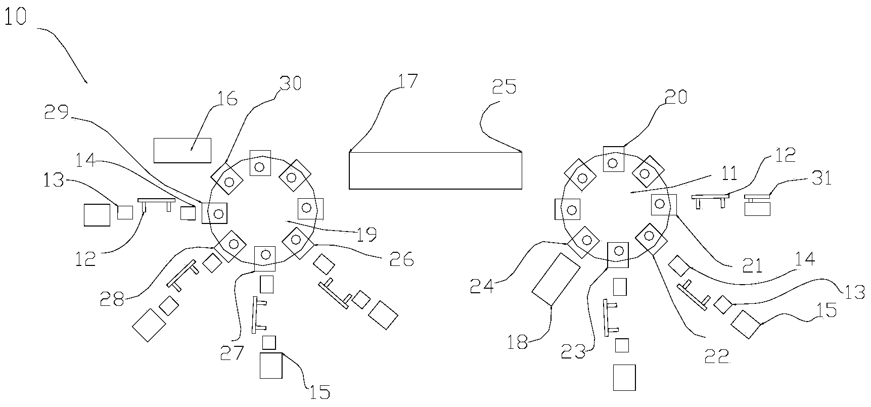
[0039] see figure 1 , figure 1 It is a schematic structural diagram of the backlight integrated assembly equipment of the present invention; in this embodiment, the backlight integrated assembly equipment 10 includes a first rotary table 11 and a second rotary table 19; FPC manual placement station 20, automatic reverse plastic frame station 21, reflective film pasting station 22, light guide plate pasting station 23, FPC assembly station 24; diffusion film pasting station set around the second rotary worktable 19 Position 26, post-enhancement 1 film station 27, post-enhancement 2 film station 28...


PUM


Abstract

The invention discloses backlight integrally assembled equipment. The equipment comprises a first rotary work table, a second rotary work table, an FPC (flexible printed circuit) manual laying position, an automatic reversing glue frame position, a reflecting film pasting position, a light guide plate pasting position, an FPC assembly position, a diffusion barrier pasting position, a light enhancement film 1 pasting position, a light enhancement film 2 pasting position, a light shading film pasting position, a compressing discharge position and a connecting position, wherein the reflecting film pasting position, the light guide plate pasting position, the diffusion barrier pasting position, the light enhancement film 1 pasting position, the light enhancement film 2 pasting position and the light shading film pasting position respectively comprise a feeding mechanism, a stripping mechanism corresponding to the feeding mechanism, a pre-alignment mechanism, an alignment mechanism and a grabbing mechanism. The equipment is high in accuracy, saves material, has a good film pasting effect andhigh operating continuity, saves manpower and is fully automatically operated during backlight assembly, and positions of the two rotary work tables can be operated in a combined manner or the position of a single rotary work table can be operated.

Description

technical field [0001] The invention relates to the technical field of backlight assembly, in particular to an integrated backlight assembly equipment. Background technique [0002] The application of random backlight in electronic equipment is more and more extensive. The backlight assembly equipment in the prior art includes a film sticking frame and a plurality of film sticking mechanical arms arranged around the film sticking frame, wherein a positioning mold is arranged on the film sticking frame, and the positioning mold Corresponding to the position of the film laminating robotic arm, the film laminating robotic arm includes the first film laminating robotic arm, the second film laminating robotic arm, the third film laminating robotic arm, the fourth film laminating robotic arm, the fifth film laminating robotic arm, the sixth film laminating robotic arm, the Seventh film-attaching robotic arm and eighth film-attaching robotic arm, the material films of these backlig...

Claims


Application Information

Patent Timeline
Patent Type & Authority Applications(China)
IPC IPC(8): B32B37/10B32B38/10
CPCB32B37/10B32B38/10
Inventor 姜光泽
Owner SHENZHEN WEIHONGKE TECH
Why Eureka
Try Eureka