
Copper shaft coupling roller

A technology of copper coupling shaft and roller, applied in the field of mechanical equipment

Inactive Publication Date: 2015-02-18
利钛威自动化系统设备(苏州)有限公司
View PDF8 Cites 0 Cited by
  • Summary
  • Abstract
  • Description
  • Claims
  • Application Information

AI Technical Summary

Problems solved by technology

[0005] On a large-scale assembly line, the workpiece travels on the assembly line, and most of them use double-speed chains. Due to the strong linkage of the double-speed chain transmission, often due to a fault, multiple places on the same assembly line stop at the same time, resulting in irreparable major losses.
At present, there is no double-speed chain replacement device with simple structure, convenient use, and flexible transmission, and a copper coupling roller that can be selectively partially stopped at any time during the workpiece transmission process.

Method used


Image

  • Copper shaft coupling roller

Examples


Embodiment Construction

[0012] The present invention will be further described below in conjunction with accompanying drawing.

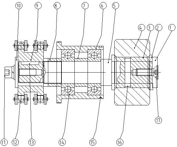
[0013] Copper coupling roller, including shaft end cover 1, spacer 2, self-lubricating copper sleeve 3, roller 4, short shaft 5, bearing sleeve 6, spacer 1 7, spacer 2 8, sprocket 9, shaft end cover 210. Screw assembly 11, chain 12, flat key 13, deep groove ball bearing 14, circlip 15, cylindrical pin 16, countersunk screw 17, characterized in that the self-lubricating copper sleeve 3 is set on one end of the short shaft 5, A roller 4 is arranged outside the self-lubricating copper sleeve 3, and one end of the self-lubricating copper sleeve 3 and the short shaft 5 is fixed by a cylindrical pin 16, and the shaft end cover 1 is limited by the spacer 2 to the self-lubricating copper sleeve 3 and the roller 4 , the shaft end cover 1 is fixed by countersunk head screws 17, the middle part of the short shaft 5 is provided with a spacer 7, and the two ends of the spacer 17 are pro...


PUM


Abstract

The invention relates to a copper shaft coupling roller, which comprises a first shaft end cover, an insulation pad, a self-lubricating copper sleeve, a roller, a short shaft, a bearing sleeve, a first spacer sleeve, a second spacer sleeve, a chain wheel, a second shaft end cover, a screw component, chains, a flat key, a deep groove ball bearing, an elastic check ring, a cylindrical pin and a sunk screw. According to the copper shaft coupling roller, by virtue of different friction coefficients between copper and steel, the copper shaft coupling roller in the technical scheme can unidirectionally rotate; in addition, when a plurality of copper shaft coupling rollers are arranged abreast for use, all shaft coupling rollers can rotate together in the same direction through the chains which are buckled in pairs only by virtue of one power mechanism, thereby driving a workpiece to move; moreover, when the workpiece is required to be positioned, the workpiece is only required to be blocked with very tiny force, and the copper shaft coupling roller at the positioned workpiece stops without influence on the transmission of the chain wheel by the chain.

Description

technical field [0001] The invention relates to the field of mechanical equipment, in particular to a copper coupling roller. Background technique [0002] Electronic technology is an emerging technology developed at the end of the nineteenth century and the beginning of the twentieth century. It developed the fastest and was most widely used in the twentieth century, becoming an important symbol of the development of modern science and technology. [0003] The first generation of electronic products centered on the electron tube. At the end of the 1940s, the first semiconductor triode was born in the world. With the characteristics of small size, light weight, power saving, and long life, it was quickly used by various countries and replaced electronic tubes in a large range. In the late 1950s, the first integrated circuit appeared in the world, which integrated many transistors and other electronic components on a silicon chip, making electronic products more miniaturized...

Claims


Application Information

Patent Timeline
Patent Type & Authority Applications(China)
IPC IPC(8): B65G23/24B65G23/04
CPCB65G23/24B65G23/04
Inventor 尹辉曾广为
Owner 利钛威自动化系统设备(苏州)有限公司
Learn More