A kind of ultrasonic metallurgy device used in rh refining furnace

A technology of ultrasonic and refining furnace, which is applied in the field of refining metallurgy to achieve the effect of improving the circulation efficiency of molten steel and improving degassing

Active Publication Date: 2016-06-29
SHANDONG IRON & STEEL CO LTD
View PDF6 Cites 0 Cited by
  • Summary
  • Abstract
  • Description
  • Claims
  • Application Information

AI Technical Summary

Problems solved by technology

[0006] The molten steel treated by RH has obvious advantages, but due to the problems of degassing and removal of inclusions, it still cannot meet the requirements of some high-quality steel products. Therefore, there is an urgent need for an RH refining device that can further improve the cleanliness of molten steel and effectively remove inclusions

Method used


Image

  • A kind of ultrasonic metallurgy device used in rh refining furnace
  • A kind of ultrasonic metallurgy device used in rh refining furnace

Examples


Embodiment 1

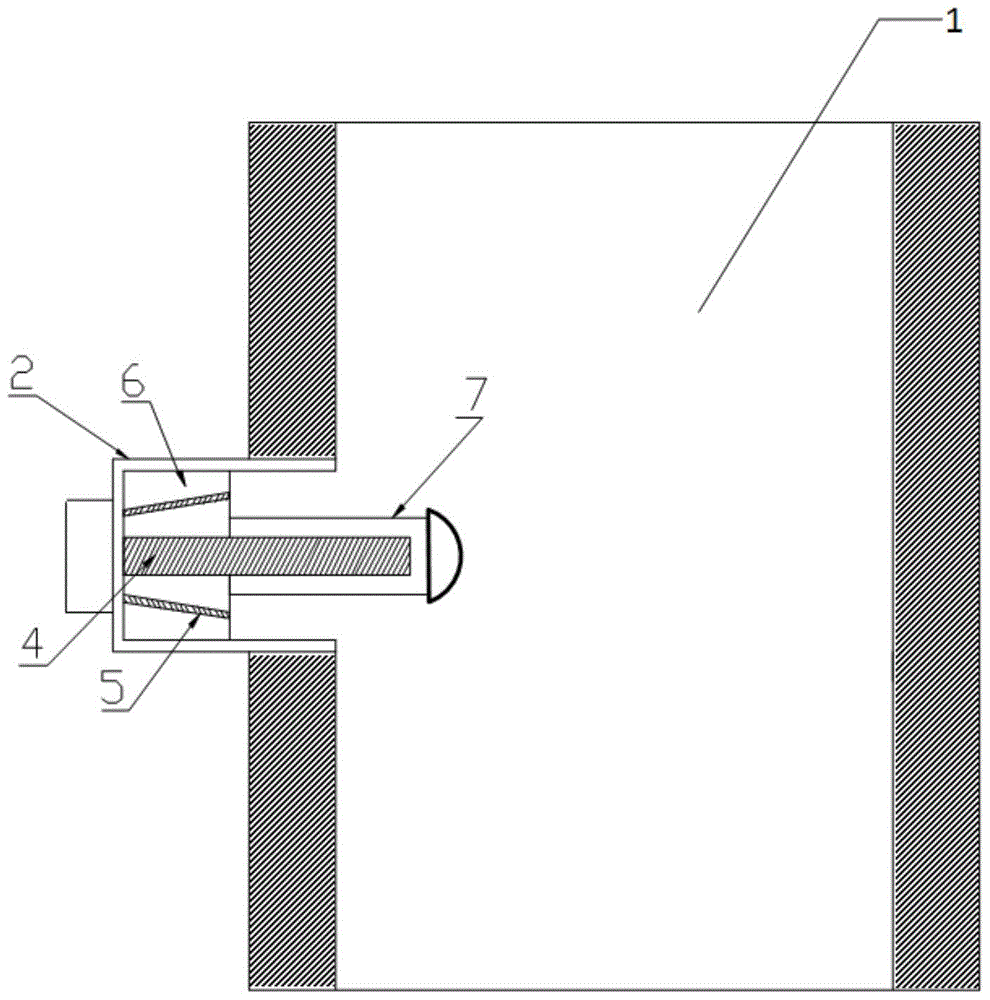
[0024] like figure 1 and figure 2 Shown, a kind of ultrasonic metallurgical device for RH refining furnace, described device comprises the outer frame 2 that is connected with RH refining furnace riser 1, and described outer frame 2 is provided with ultrasonic generator 6 and is used for ultrasonic generator The ultrasonic wave generated by 6 is input to the ultrasonic working head 7 in the riser 1; the outer frame 2 is also provided with an argon blowing pipe 4 communicating with the riser 1 and six argon seals surrounding the argon blowing pipe 4 for air sealing. Tube 5; the argon blowing tube 4 and six argon sealing tubes 5 pass through the outer frame 2 and are connected to the argon gas source.

[0025] One end of the argon blowing pipe 4 extending into the riser 1 is in the shape of a shower head.

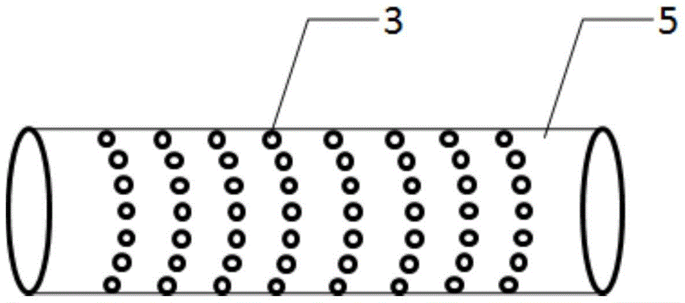
[0026] Eight circles of through holes 3 are provided in a circular shape on the outer surface of the argon-sealed tube 5 .

[0027] The ultrasonic generator 6 is arranged...


PUM


Abstract

The invention discloses an ultrasonic metallurgical device for an RH refining furnace, which comprises an outer frame (2) connected with a riser (1) of the RH refining furnace, wherein an ultrasonic generator (6) and an ultrasonic working head (7) for inputting ultrasonic generated by the ultrasonic generator (6) into the riser (1) are arranged in the outer frame (2); an argon blowing pipe (4) communicated with the riser (1), a surrounding argon blowing pipe (4) and a plurality of argon sealing pipes (5) for hermetic seal are also arranged in the outer frame (2); and the argon blowing pipe (4) and the argon sealing pipes (5) are connected with an argon source after penetrating through the outer frame (2). The metallurgical device can enhance the molten steel circulation efficiency of the RH refining furnace and improve the degassing and inclusion removal effects.

Description

technical field [0001] The invention belongs to the technical field of refining metallurgy, in particular, the invention relates to an ultrasonic metallurgical device for RH refining furnace. Background technique [0002] The full name of RH refining is RH vacuum circulation degassing refining method. Invented by the Germans in 1959, RH is the first letter of the two German manufacturers that adopted RH refining technology at that time. The application of vacuum technology in steelmaking began in 1952. At that time, when people produced silicon steel with a silicon content of about 2%, slag often appeared during the pouring process. After various tests, it was finally found that hydrogen and Nitrogen is the main reason for the generation of slag, which leads to the failure of pouring or the production of waste products after rolling. Then various vacuum refining technologies began to appear, such as vacuum ingot casting method, ladle trickle degassing method, ladle degassin...

Claims


Application Information

Patent Timeline
Patent Type & Authority Patents(China)
IPC IPC(8): C21C7/10C21C7/072
Inventor 张冠锋李小雄张丽董洪壮刘美任琪司胜春赵健刘成宝韩杰张炯
Owner SHANDONG IRON & STEEL CO LTD
Why Eureka
Try Eureka