Gas-liquid separation-type casing gas recycling device

A recovery device, gas-liquid separation technology, applied in the fields of production fluids, wellbore/well components, earth-moving drilling, etc., can solve the problem of valve core freezing blocking and other problems, and achieve the effect of solving the freezing blocking problem

Active Publication Date: 2015-02-18
PETROCHINA CO LTD
View PDF10 Cites 7 Cited by
  • Summary
  • Abstract
  • Description
  • Claims
  • Application Information

AI Technical Summary

Problems solved by technology

[0003] The purpose of the present invention is to provide a gas-liquid separation casing gas recovery device to solve the problem of freezing of the valve core and achieve the purpose of completely recovering the casing gas

Method used


Image

  • Gas-liquid separation-type casing gas recycling device
  • Gas-liquid separation-type casing gas recycling device

Examples


Embodiment 1

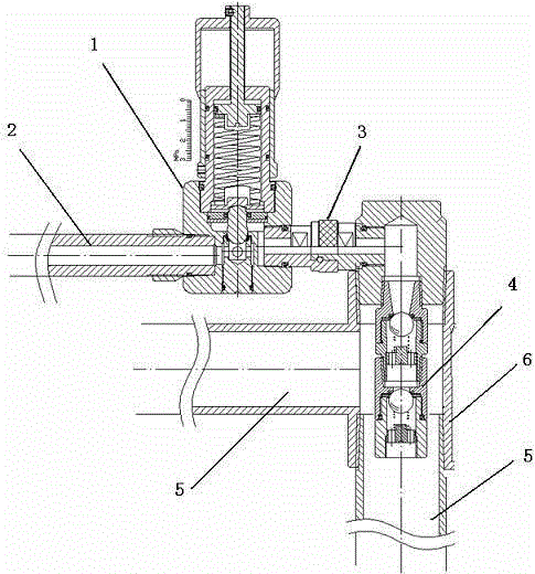
[0019] In order to solve the freezing problem of the spool and achieve the purpose of completely recovering the casing gas, this embodiment provides a method such as figure 1 The gas-liquid separation casing gas recovery device shown includes a constant pressure release valve 1 and a one-way valve 4. An air inlet 17 is provided on one side of the constant pressure release valve 1, and the air inlet 17 is connected to the air inlet pipeline. 2. Connected by threads, the other side of the constant pressure release valve 1 is provided with an exhaust hole 18, which is connected to the quick joint 3, and the other end of the quick joint 3 is connected to a three-way pipe 6, the said The other two ends of the three-way pipe 6 are respectively connected with production process pipelines 5, and the one-way valve 4 is installed at the intersection in the three-way pipe 6;

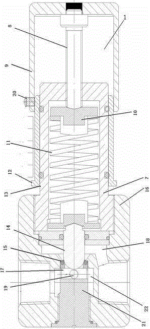
[0020] Constant pressure release valve 1 such as figure 2 As shown, it includes a valve body 16, the valve bod...

Embodiment 2

[0025] On the basis of embodiment 1, working process of the present invention is as follows:

[0026] Such as figure 1 As shown, in the actual production process of the gas-liquid separation sleeve gas recovery device of the present invention, the check valve 4 is inserted and fixed in the production process 5, which can achieve the effect of heat tracing and antifreezing.

[0027] In the gas-liquid separation casing gas recovery device, a pressure value must be set before the constant pressure release valve 1 works. First, loosen the bolt 20, slide the pressure regulating cap 9, and slide the pressure regulating cap 9 to the corresponding pressure of the scale sleeve 14. After the scale, tighten the bolt 20. At this time, the pressure regulating cap 9 acts on the ejector rod 8 connected to its top end. The ejector rod 8 transmits the pressure through the constant pressure spring 11 and the constant pressure piston 14. The pressure is directly displayed on the scale sleeve 12 ...


PUM


Abstract

The invention relates to a gas-liquid separation-type casing gas recycling device, comprising a constant pressure gas release valve and a check valve, wherein a gas inlet hole is formed in one side of the constant pressure gas release valve; the gas inlet hole is connected with a gas inlet pipeline; a gas exhaust hole is formed in the other side of the constant pressure gas release valve; the gas exhaust hole is connected with a fast joint; the other end of the fast joint is connected with a three-way pipe; the other two ends of the three-way pipe are respectively connected with production process pipelines; the check valve is arranged in the intersection position in the three-way pipe; the constant pressure gas release valve comprises a valve body; the valve body is internally provided with a piston; a valve holder, of which the upper end is provided with a valve ball, is connected below the piston; a valve seat is arranged at the outer side of the valve holder in a sleeving manner; the gas inlet hole is formed in one side of the valve seat, and is communicated with the valve holder which is provided with the valve ball; the gas exhaust hole is formed in the other side of the valve body; the gas exhaust hole is placed above the position where the piston is in contact with the valve holder. According to the gas-liquid separation-type casing gas recycling device, the check valve can prevent crude tar from flowing to the constant pressure gas release valve by means of tracing heat of heat of the field crude tar, so that the gas-liquid separation is realized, and the problem that a constant pressure valve is frozen and blocked in winter is solved.

Description

technical field [0001] The invention belongs to the technical field of oil recovery engineering, and in particular relates to a gas-liquid separation casing gas recovery device. Background technique [0002] As the front-end production unit of the upstream production link of the oil industry, the well site has many and scattered points in the oil field. Due to the restriction of technical means, the back pressure of the wellhead in the remote well site is high, so it is necessary to install a heating furnace in the well site, and its fuel is the associated gas of the wellhead casing. , the domestic oilfield casing gas recovery process mainly adopts surface recovery technology, mainly the wellhead constant pressure valve gas collection and mixed transportation. The constant pressure valve absorbs heat when the gas is released. When the back pressure of crude oil in the production process is higher than the exhaust pressure of the constant pressure valve, the crude oil flows ...

Claims


Application Information

Patent Timeline
Patent Type & Authority Applications(China)
IPC IPC(8): E21B43/00
CPCE21B43/00
Inventor 王曼魏立军王林平晏耿成覃川张倩杨会丰刘一山郑刚冯建设程颢
Owner PETROCHINA CO LTD
Why Eureka
Try Eureka