A gas-liquid separation casing gas recovery device
A recovery device, gas-liquid separation technology, applied in the fields of production fluids, wellbore/well components, earth-moving drilling, etc., can solve the problem of valve core freezing blocking and other problems, and achieve the effect of solving the freezing blocking problem
- Summary
- Abstract
- Description
- Claims
- Application Information
AI Technical Summary
Problems solved by technology
Method used
Image
Examples
Embodiment 1
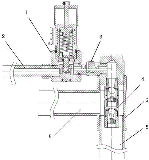
[0019] In order to solve the freezing problem of the spool and achieve the purpose of completely recovering the casing gas, this embodiment provides a method such as figure 1 The gas-liquid separation casing gas recovery device shown includes a constant pressure release valve 1 and a one-way valve 4. An air inlet 17 is provided on one side of the constant pressure release valve 1, and the air inlet 17 is connected to the air inlet pipeline. 2. Connected by threads, the other side of the constant pressure release valve 1 is provided with an exhaust hole 18, which is connected to the quick joint 3, and the other end of the quick joint 3 is connected to a three-way pipe 6, the said The other two ends of the three-way pipe 6 are respectively connected with production process pipelines 5, and the one-way valve 4 is installed at the intersection in the three-way pipe 6;
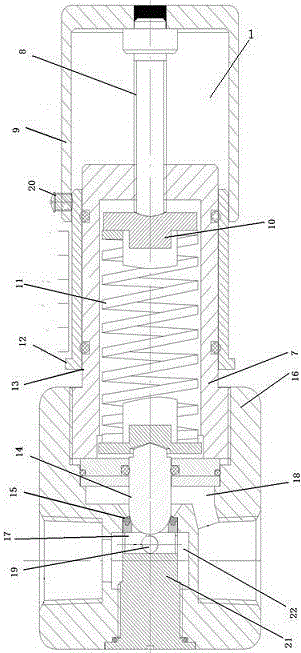
[0020] Constant pressure release valve 1 such as figure 2 As shown, it includes a valve body 16, the valve bod...
Embodiment 2
[0025] On the basis of embodiment 1, working process of the present invention is as follows:
[0026] Such as figure 1 As shown, in the actual production process of the gas-liquid separation sleeve gas recovery device of the present invention, the check valve 4 is inserted and fixed in the production process 5, which can achieve the effect of heat tracing and antifreezing.
[0027] In the gas-liquid separation casing gas recovery device, a pressure value must be set before the constant pressure release valve 1 works. First, loosen the bolt 20, slide the pressure regulating cap 9, and slide the pressure regulating cap 9 to the corresponding pressure of the scale sleeve 14. After the scale, tighten the bolt 20. At this time, the pressure regulating cap 9 acts on the ejector rod 8 connected to its top end. The ejector rod 8 transmits the pressure through the constant pressure spring 11 and the constant pressure piston 14. The pressure is directly displayed on the scale sleeve 12 ...
PUM
 Abstract
Description
Claims
Application Information
 - R&D
- Intellectual Property
- Life Sciences
- Materials
- Tech Scout
- Unparalleled Data Quality
- Higher Quality Content
- 60% Fewer Hallucinations
Browse by: Latest US Patents, China's latest patents, Technical Efficacy Thesaurus, Application Domain, Technology Topic, Popular Technical Reports.
© 2025 PatSnap. All rights reserved.Legal|Privacy policy|Modern Slavery Act Transparency Statement|Sitemap|About US| Contact US: help@patsnap.com


