Convenient-to-dismount diaphragm pump

A technology of diaphragm pumps and diaphragms, which is applied in the field of volumetric pumps, can solve problems such as difficulty in improving tensile performance and fatigue resistance, time-consuming and labor-intensive labor intensity, complicated disassembly and assembly of external pipelines, etc., and achieves high maintenance and replacement efficiency and low labor costs. Reduced strength and labor-saving effects

Active Publication Date: 2015-02-18
HEFEI UNIV OF TECH +1
View PDF5 Cites 4 Cited by
  • Summary
  • Abstract
  • Description
  • Claims
  • Application Information

AI Technical Summary

Problems solved by technology

Due to the material of the diaphragm itself and the structural characteristics of the straight plate, it has been difficult to improve its own tensile properties and fatigue resistance. After a long period of use, the fatigue and cracking of the diaphragm is inevitable, which must be monitored from time to time and when needed. shut down for replacement
However, the problem is that when the traditional diaphragm pump is working, the diaphragm is sandwiched between the two halves of the diaphragm pump, and the liquid pipelines are also directly fixed on the two halves, while the pump body The disassembly direction just cannot avoid the above direction
As a result of the above situation, once the pump body needs to be disassembled to monitor or replace the diaphragm, the hydraulic source piping, medium inlet and outlet pipes, and even all the pipelines connected to the orifices of the pump must be removed before the pump body can be disassembled. Inspect the working status of the internal diaphragm, and then judge whether to replace and maintain
The most difficult point of its disassembly work is that the pipelines connected to each orifice of the pump are often fixed at other equipment and their positions are stable with each other. How to quickly disassemble the pipeline without affecting other equipment becomes difficult, at least It is completely impossible to realize on the current equipment; it is often time-consuming, labor-intensive and labor-intensive, and the disassembly and assembly of the external pipeline is already extremely complicated, which brings great troubles to the on-site maintenance personnel.

Method used


Image

  • Convenient-to-dismount diaphragm pump
  • Convenient-to-dismount diaphragm pump
  • Convenient-to-dismount diaphragm pump

Examples


Embodiment Construction

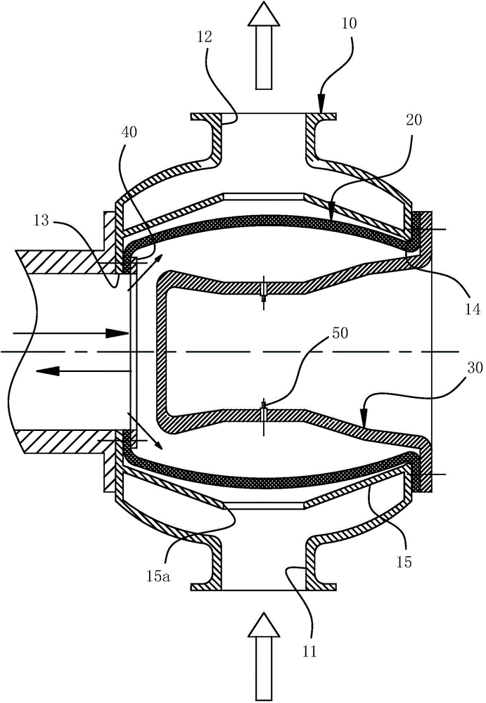
[0028] For ease of understanding, here in conjunction with accompanying drawing, to the concrete implementation structure of the present invention, be further described as follows:

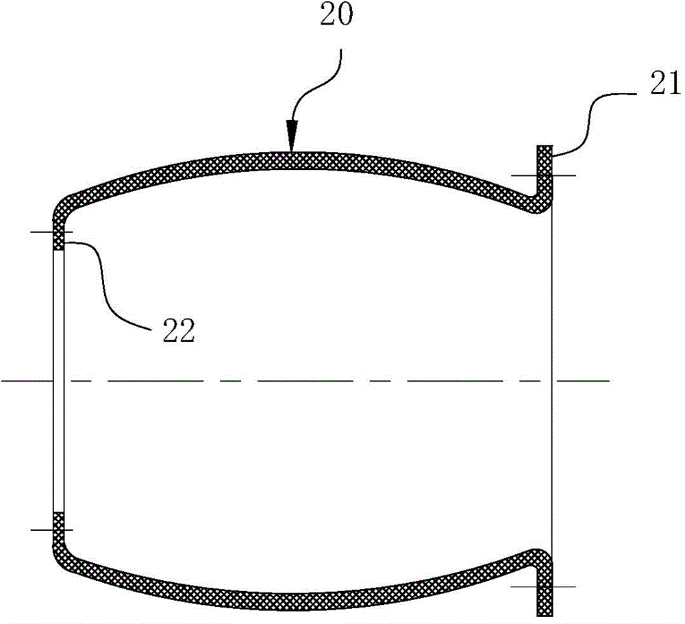
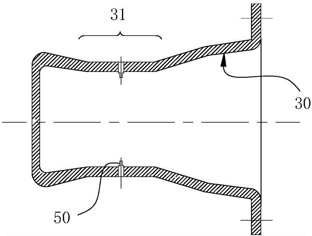
[0029] Concrete structure of the present invention, as Figure 1-3 As shown, it is mainly composed of a drum-shaped pump body 10 with a convex arc-shaped drum body that constitutes a hydraulic cavity and a medium circulation space. A hydraulic hole 13 connecting the external hydraulic station and the hydraulic cavity inside the pump is arranged through the drum surface on one side of the pump body 10 , and a maintenance hole 14 is arranged on the drum surface on the other side. The convex arc-shaped drum body of the pump body 10 is coaxially arranged to communicate with the medium chamber in the pump cavity to pump the medium inlet hole 11 and the liquid outlet hole 12, and the liquid inlet hole 11 and the liquid outlet hole 12 are respectively connected to the external upper discharge device and...


PUM


Abstract

The invention belongs to the field of a volume pump, and particularly relates to a convenient-to-dismount diaphragm pump with the advantages that the monitoring can be realized in proper time, and a diaphragm leaf can be fast dismounted and replaced on line. The convenient-to-dismount diaphragm pump comprises a pump body and the diaphragm leaf, wherein liquid inlet and outlet holes and hydraulic holes are respectively formed in the pump wall of the pump body, a located pump cavity of the liquid inlet and outlet holes and a located pump cavity of the hydraulic holes are separated through the diaphragm leaf, the pump body also comprises a repair hole, the repair hole is sealed by an end cover, the appearance of the diaphragm leaf is of a sleeve-shaped structure, a pipe opening formed at one end of the diaphragm leaf is fixedly connected with the hole end surface of the hydraulic holes through screw bolts, a pipe opening formed in the other end of the diaphragm leaf extends towards the repair hole and is provided with an outer flange, the outer flange is arranged in a way of being matched with the surfaces between the hole ends, positioned at the outer wall parts of the the pump body, of the repair hole, and the end cover is pressed on the outer flange and is arranged in a way of being fixedly connected with screw bolts arranged between the pump walls of the pump body. The convenient-to-dismount diaphragm pump has the advantages that the monitoring and dismounting problems of the exiting conventional diaphragm pump can be effectively solved, the dismounting convenience and the maintenance replacement efficiency are high, and the work intensity of maintenance personnel can be greatly reduced.

Description

technical field [0001] The invention belongs to the field of positive displacement pumps, and in particular relates to a detachable diaphragm pump capable of timely monitoring and quick disassembly and replacement of diaphragms online. Background technique [0002] Diaphragm pump is a special form of positive displacement pump, which is widely used in petrochemical, coal chemical and oil fields and other fields. At present, the general structure of the diaphragm pump includes a closed pump chamber. By arranging a straight diaphragm in the pump chamber, the above pump chamber is divided into two mutually isolated working chambers, and the two working chambers are changed by the back and forth agitation of the diaphragm. This is described in related patents with the publication number CN 103233883A entitled "A Diaphragm Seawater Pump" and other related patents. Since the core of the diaphragm pump is the elastic expansion and contraction of the diaphragm, it can also be said ...

Claims


Application Information

Patent Timeline
Patent Type & Authority Applications(China)
IPC IPC(8): F04B43/06F04B53/22F04B53/00F04B49/00
Inventor 柴立平李强何玉杰张杰石海峡
Owner HEFEI UNIV OF TECH
Why Eureka
Try Eureka