Relay capable of preventing large-current contact separation

A contact separation, electromagnetic relay technology, applied in the direction of electromagnetic relay, relay, electromagnetic relay detailed information, etc., can solve the problems of increasing arc ablation, easy separation of contacts, contact bonding, etc., to solve the problem of contact bounce, Avoid contact bonding and solve the effect of contact separation

Active Publication Date: 2015-02-18
ZHEJIANG CHINT ELECTRIC CO LTD
View PDF4 Cites 16 Cited by
  • Summary
  • Abstract
  • Description
  • Claims
  • Application Information

AI Technical Summary

Problems solved by technology

The inrush current required by the magnetic latching relay for electric energy meters is more than 30 times the rated current. The electromotive force existing in the contact structure of the traditional magnetic latching relay is contact repulsion, and the electrodynamic force will make the contacts easy to separate during the inrush current test; in addition , when the product is closed, the electric power increases the probability of bouncing, especially when opening and closing a large ampere current, the bouncing is obvious, which increases arc ablation
In the prior art, when the contacts are closed, the current direction of the second lead-out piece and the moving reed are opposite and generate a magnetic field with each other. The magnetic field makes the electromagnetic force generated by the moving reed have the same direction as the driving force generated by the push card. The structure of the scheme is complex, and there is a risk of contact bonding due to excessive contact pressure during the overload test

Method used


Image

  • Relay capable of preventing large-current contact separation
  • Relay capable of preventing large-current contact separation
  • Relay capable of preventing large-current contact separation

Examples


Embodiment Construction

[0026] The following is attached Figures 1 to 10 The given examples further illustrate the specific implementation of the electromagnetic relay for preventing separation of high-current contacts of the present invention. The electromagnetic relay of the present invention is not limited to the description of the following embodiments.

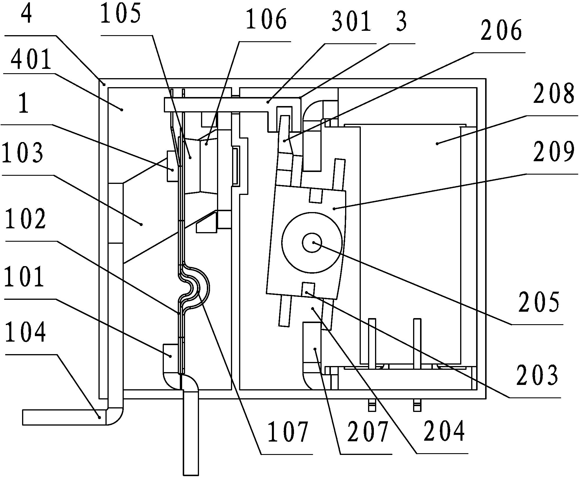
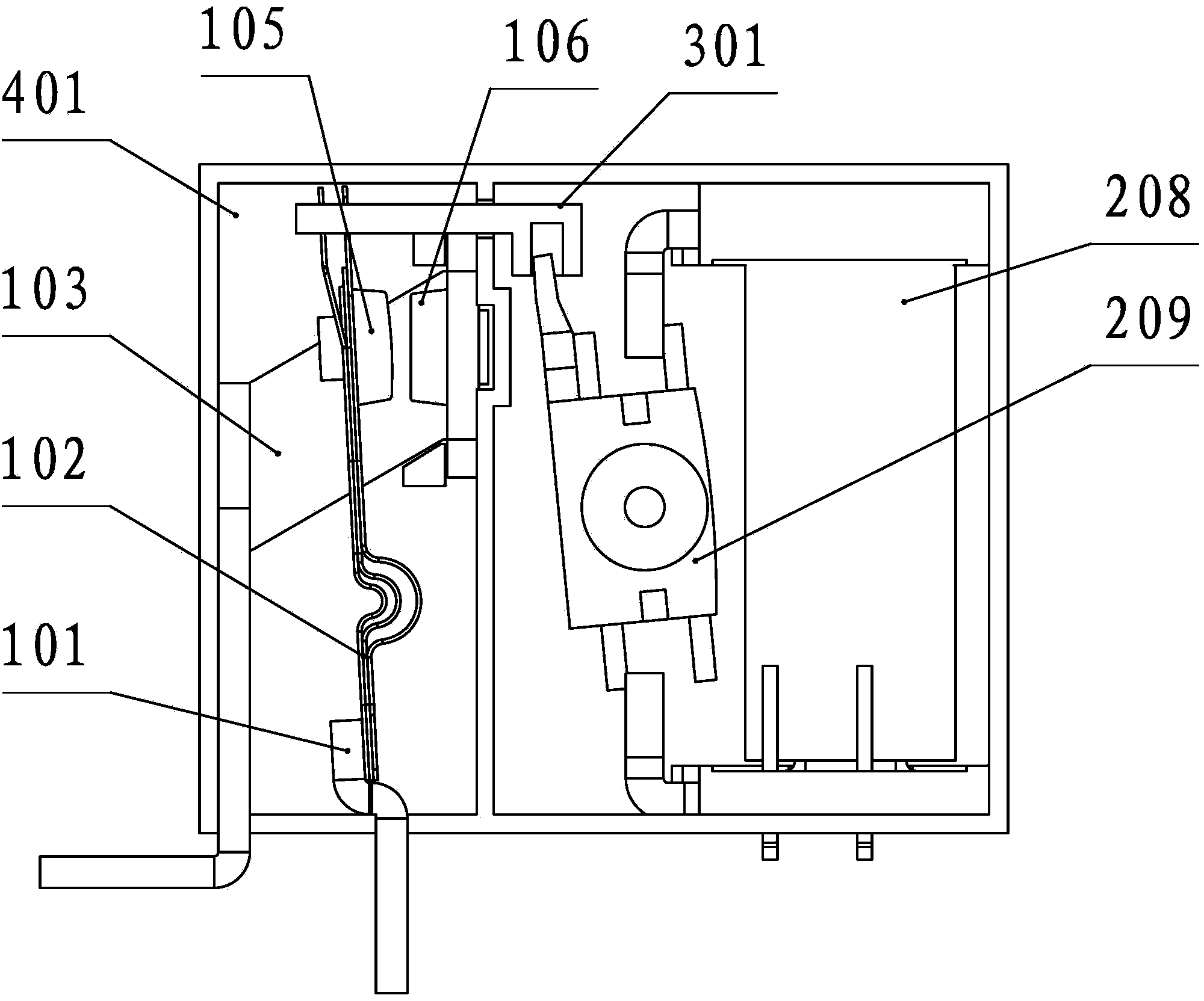
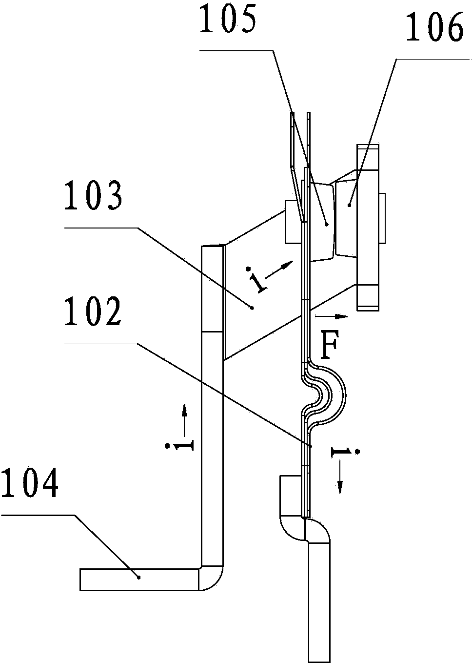
[0027] Such as Figure 1-6 As shown, the electromagnetic relay of the present invention includes a housing 4 and a contact system 1 , an electromagnetic system 2 and a pusher 3 arranged in the housing 4 . The contact system 1 includes a static piece 103 with a static contact 106 and a moving reed 102 with a moving contact 105; the moving reed 102 is connected with the pusher 3, and the pusher 3 is connected with the electromagnetic system 2, and the electromagnetic system 2 The moving reed 102 can be driven to swing by the pusher 3 to realize the opening and closing of the moving contact 105 and the static contact 106, and the connection or d...


PUM


Abstract

A relay capable of preventing large-current contact separation comprises a shell, a contact system, an electromagnetic system and pushing part, wherein the contact system, the electromagnetic system and the pushing part are arranged in the shell. The contact system comprises a static piece provided with a static contact and a movable contact spring provided with a movable contact; the movable contact spring is connected with the pushing part which is connected with the electromagnetic system, the electromagnetic system drives the movable contact spring to swing through the pushing part to have the movable contact and the static contact separated or jointed, the static piece is of a U-shaped structure, the static contact is arranged on the inner wall of the U-shaped structure, the movable contact spring extends into the cavity of the U-shaped structure, the movable contact is arranged corresponding to the static contact 106, and the direction of electrodynamic force F is the direction from the movable contact to the static contact when the contact system is closed. The relay is simple in structure and low in cost; by the arrangement of the static piece of the U-shaped structure, the electrodynamic force F is enabled to push the movable contact to press the static contact when the contact system is closed, and problems about the contact separation and bouncing of the contacts during large current can be effectively solved.

Description

technical field [0001] The invention relates to a relay, in particular to an electromagnetic relay for preventing separation of high-current contacts. Background technique [0002] The magnetic latching relay is a new type of relay. Like other electromagnetic relays, it can automatically switch on and off the circuit. The normally closed or normally open state of the magnetic latching relay is completely dependent on the effect of the permanent magnet, and the switching state of the relay is triggered by a pulse electric signal of a certain width. With the development of electric energy meters, magnetic latching relays have become an indispensable and important part of electric energy meters. The inrush current required by the magnetic latching relay for electric energy meters is more than 30 times the rated current. The electromotive force existing in the contact structure of the traditional magnetic latching relay is contact repulsion, and the electrodynamic force will ma...

Claims


Application Information

Patent Timeline
Patent Type & Authority Applications(China)
IPC IPC(8): H01H50/54
CPCH01H50/16H01H50/54
Inventor 王联长蒲启成
Owner ZHEJIANG CHINT ELECTRIC CO LTD
Why Eureka
Try Eureka