Slag crusher

A slag and mechanical treatment technology, applied in the field of slag crushers, can solve the problems of limited production capacity, uncontrolled, uncertain treatment density of slag flow, etc., and achieve the effect of high treatment density

Inactive Publication Date: 2015-02-25
TARTECH ECO INDS
View PDF13 Cites 0 Cited by
  • Summary
  • Abstract
  • Description
  • Claims
  • Application Information

AI Technical Summary

Problems solved by technology

[0006] A disadvantage of the previously known devices with continuous, extended rotor planes is that the treatment density of the slag stream is uncertain or uncontrolled
[0008] The disadvantage of this is that the slag flow guided through the treatment chamber may have to be conveyed to the treatment chamber again, so that the overall production capacity is limited

Method used


Image

  • Slag crusher
  • Slag crusher
  • Slag crusher

Examples


Embodiment Construction

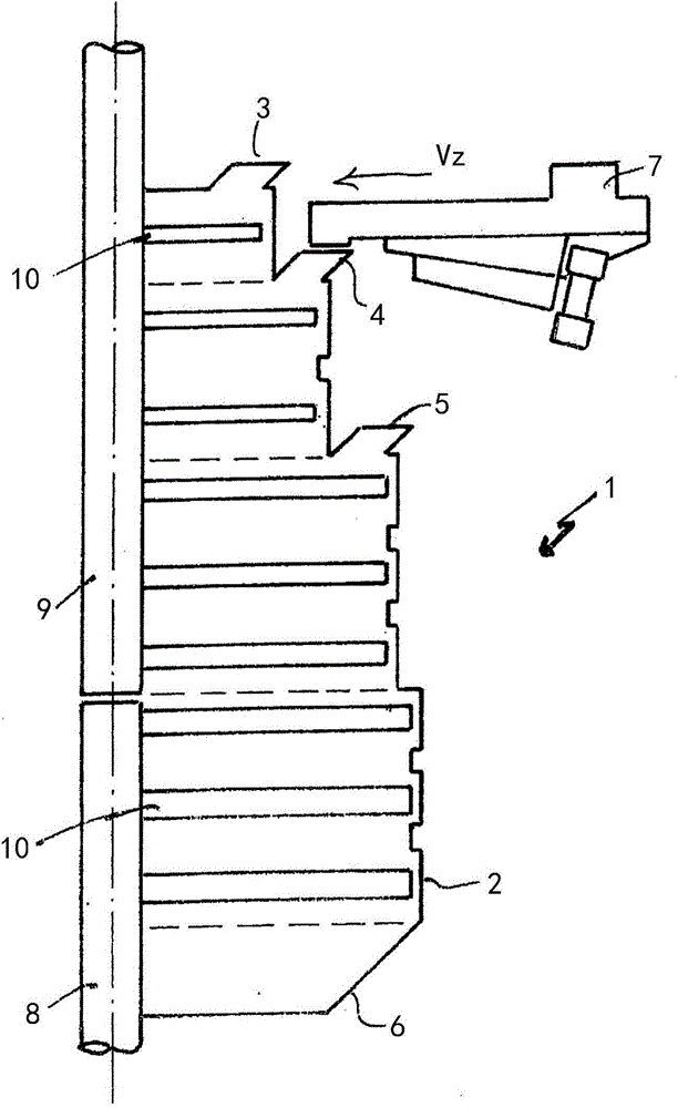
[0049] like figure 1 As shown, the treatment device or crusher 1 has a housing 2 . In the embodiment shown, the housing 2 has filling openings 3 , 4 , 5 . These filling openings can be closed by caps, not shown. An outlet opening 6 is provided in the lower region.

[0050] In the illustrated embodiment, a slag conveying device is shown in the region of the filling opening 4 , with which the slag flow can be dimensioned or controlled.

[0051] In the vertical center of the housing 2 are shown drive shafts 8 , 9 on which a plurality of rotor elements 10 are fastened. In this embodiment, these rotor elements are shown as paddles, but could also be impactors fixed to chains or the like.

[0052] The slag crusher 1 works like this: the slag is loaded into one or more filling ports 3, 4, 5, and then these slags pass through different rotor planes and are processed accordingly by the rotor, wherein the slag The components strike the impact element and are thereby split or crushe...


PUM


Abstract

A device for the mechanical processing of slags by impact elements within a processing chamber includes a housing having a filling opening and a discharge opening in which at least one rotor with impact elements rotating about an axle is placed. The slags pass through the rotor on the way from the filling opening to the discharge opening and the rotor is configured in such a way that it has a processing density of at least 90% of the slags of a slag flow that has been fed.

Description

technical field [0001] The invention relates to a slag crusher. The slag crusher is a device that uses impact elements to mechanically process slag. Background technique [0002] In the context of the present invention, slag means a mixture of materials of different densities and possibly also different concentrations. It is known to leave slag when ore is processed, or slag can also be combustion residues. Especially in the process of waste recycling, slag will be left when burning rubbish. However, different types of landfills and other miscellaneous materials of the aforementioned type are also referred to as slag in the present invention. In each case, this type of slag includes, for example, earth, gravel, stones and various inclusions, namely ferrous metals, non-ferrous metals, light metals, precious metals and the like. It is known to achieve mechanical comminution or disintegration of the slag by comminuting the slag with a hammer mill or impact mill. [0003] I...

Claims


Application Information

Patent Timeline
Patent Type & Authority Applications(China)
IPC IPC(8): B02C19/00
CPCB02C13/286B02C2013/2808B02C13/14B02C2013/2869B02C13/28B02C2013/2816B02C19/0012
Inventor 克劳斯·格朗霍兹
Owner TARTECH ECO INDS
Why Eureka
Try Eureka