High-density DBF multi-path multi-target signal processing device

A signal processing device, high-density technology, applied in radar, anti-interference communication, high-density DBF multi-channel multi-target signal processing device, sonar field, can solve the problems of small size and high signal processing density

Pending Publication Date: 2021-06-18
10TH RES INST OF CETC
View PDF17 Cites 0 Cited by
  • Summary
  • Abstract
  • Description
  • Claims
  • Application Information

AI Technical Summary

Problems solved by technology

[0006] The purpose of the present invention is to provide a high-density digital beamforming DBF multi-channel multi-target signal processing device with small volume and high sign

Method used


Image

  • High-density DBF multi-path multi-target signal processing device
  • High-density DBF multi-path multi-target signal processing device
  • High-density DBF multi-path multi-target signal processing device

Examples


Embodiment 1

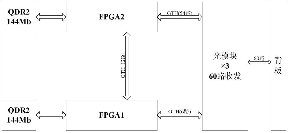
[0025] refer to figure 2 . The 6U board can use 3 optical modules to configure the digital signal processor DSP to realize the photoelectric-to-optical conversion of 60 high-speed signals. The 54 optical signals received by the digital signal processor DSP block are converted into 54 channels through the optical module through the backplane, and the high-speed The GTH electrical signal of the transceiver is demodulated, decoded, and de-interleaved through FPGA2, and the processed data is sent to FPGA1 through 12 GTH electrical signals for data modulation, demodulation capture, encoding, and compression of the encoded data stored in the memory , The data processed by FPGA1 is sent to an optical module through 6 GTH electrical signals for electro-optical conversion, and the converted 6 optical signals are sent to the backplane to other boards for subsequent digital signal processing. QDR is mainly used for data encoding and compression, and QDR2 can be a 144Mbit memory.

Embodiment 2

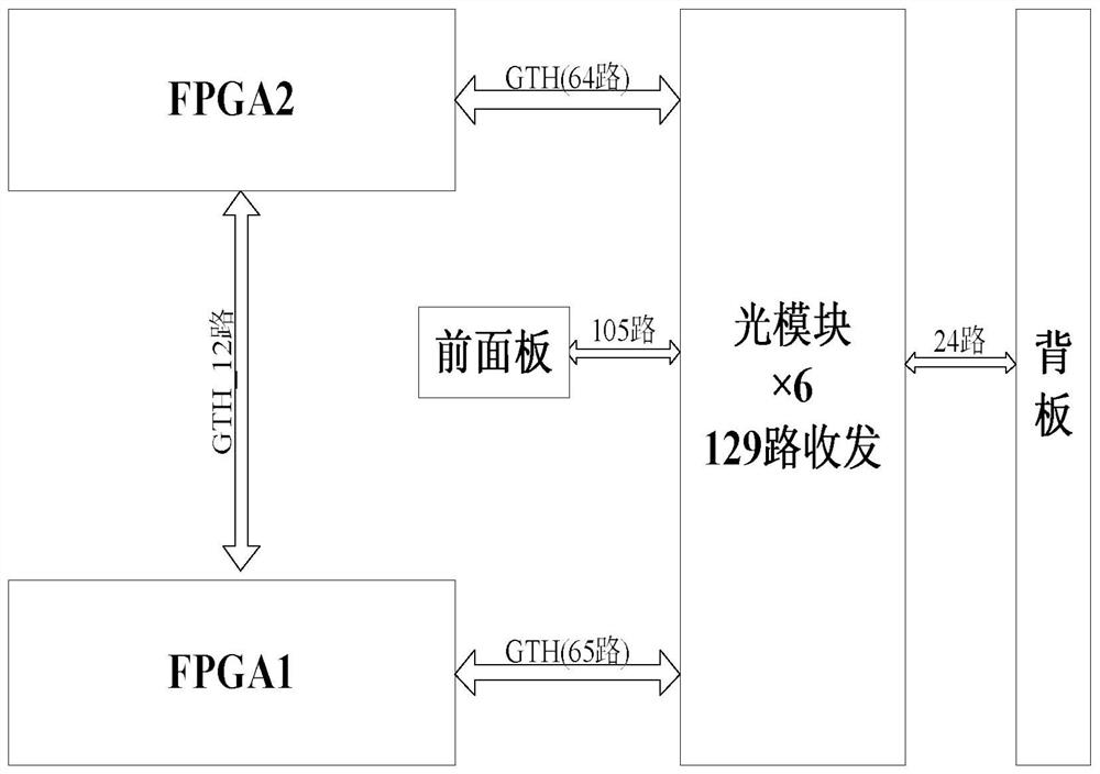
[0027] refer to image 3 . The beam processing module can use 6 optical modules to configure the beam processing module to realize the photoelectric-to-optical conversion of 129 high-speed signals. Among them, the 105 optical signals on the front panel are converted into 105 electrical signals through the optical module, which are respectively sent to FPGA1 65 channels, to FPGA2 has 64 channels, and FPGA1 and FPGA2 perform high-speed data interaction through 12-channel high-speed transceiver GTH, complete real-time beam zeroing of DBF signals, digital beam synthesis DBF weighting, and 24 channels of electrical signals after processing are passed through an optical module. The electro-optical conversion is converted into optical signals and sent to the backplane to other boards for subsequent digital signal processing.

Embodiment 3

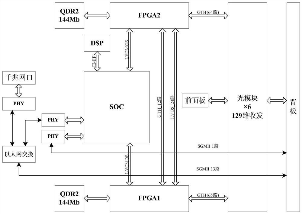
[0029] refer to Figure 4 . The 6U board can use 4 optical modules to configure a high-speed photoelectric conversion module to realize the photoelectric-to-electrical conversion of 76 high-speed signals. The 12 optical signals on the front panel and the 64 optical signals on the back panel are converted into 76 electrical signals through the photoelectric conversion module. 64 channels of FPGA2 and 12 channels of FPGA1, data interaction and routing between FPGA1 and FPGA2 through the 12-channel high-speed transceiver GTH, and then the routed data is sent to the Four optical modules are used for electro-optical conversion, and the converted 76 optical signals are sent to 64 channels on the backplane and 12 channels on the front panel, which can realize high-speed exchange of 78 optical signals. The 6U board uses an Ethernet switch chip to realize data exchange with Ethernet. The SOC connects 1 PHY to the switch chip to manage the Ethernet switch chip, and connects 1 PHY to SG...


PUM


Abstract

A high-density DBF multi-path multi-target signal processing device disclosed by the invention is small in size and high in signal processing density. According to the technical scheme, in a comprehensive processing pool, an FPGA1 and an FPGA2 are mutually connected with a system-level chip of an external gigabit network analog-digital hybrid circuit PHY chip to realize the transmission of high-speed serial signals, the FPGA1 and the FPGA2 are respectively connected with 1-6 optical modules through a high-speed transceiver GTH (65-path) and a GTH (64-path), interference direction finding processing and wave beam zero setting signals are sent to a high-density layout optical module for local digital beam forming DBF processing, the optical module sends zero setting requirements and real-time wave beam pointing to a wave beam zero setting function module, a digital beam forming DBF weighted value is generated through calculation, a local DBF processing result is converted into 129 paths of optical signals through the optical module, and remote control, remote measurement, framing, coding and modulation output of multi-target uplink signals are realized.

Description

technical field [0001] The present invention relates to the fields of digital beam forming, high-speed optical fiber transmission, high-speed data exchange, anti-jamming, signal processing, etc., and particularly relates to a high-density DBF multiplexer mainly used for radar, sonar, and anti-jamming communication to complete spatial filtering and positioning Multi-target signal processing device. Background technique [0002] With the rapid progress of modern digital signal processing theory and computer technology, digital beamforming technology has become one of the hot spots in current radar research and application. Digital beamforming is a beamforming technology established with the development of digital signal processing technology, which can use complex digital signal processing to process information. With the development of signal processing technology, the signal environment is becoming more and more complex, and the signal tends to be diversified, high-density,...

Claims


Application Information

Patent Timeline
IPC IPC(8): G01S7/28G01S7/35G01S7/523G01S7/534H04L12/02
CPCG01S7/28G01S7/35G01S7/523G01S7/534H04L12/02
Inventor 吴江刘盛利刘可陈能王忆蒙
Owner 10TH RES INST OF CETC
Why Eureka
Try Eureka