
Movable negative pressure purification device and mobile negative pressure purification system

A purification device and negative pressure technology, applied in heating methods, chemical instruments and methods, and dust removal, etc., can solve problems such as pollution and corrosion of driving structures, achieve wide applicability, reduce maintenance and replacement frequency, and improve efficiency.

Active Publication Date: 2016-07-13
庄明
View PDF10 Cites 0 Cited by
  • Summary
  • Abstract
  • Description
  • Claims
  • Application Information

AI Technical Summary

Problems solved by technology

[0003] The purpose of the present invention is to provide a movable negative pressure purification device and a movable negative pressure purification system to solve the problem that the driving structure in the negative pressure purification device is easily polluted and corroded in the prior art

Method used


Image

  • Movable negative pressure purification device and mobile negative pressure purification system
  • Movable negative pressure purification device and mobile negative pressure purification system
  • Movable negative pressure purification device and mobile negative pressure purification system

Examples


Embodiment 1

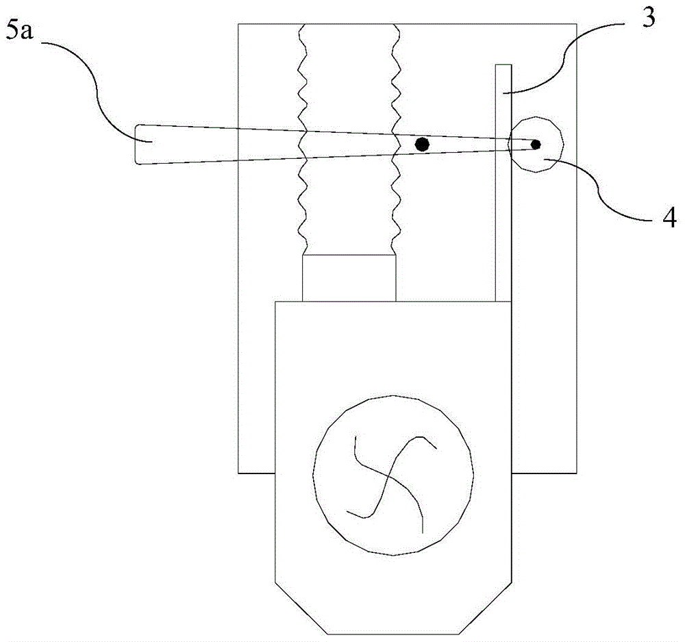
[0037] Such as image 3 As shown, the driving source 5 is a long manual handle 5a, one end of the manual handle 5a is connected to the rotation axis of the transmission gear 4, and the other end of the manual handle 5a protrudes from the housing 1 for manual swing. By manually swinging the manual handle 5a, the transmission gear 4 is driven to rotate, and then the rack 3 is driven to move, so that the air cylinder 2 realizes telescopic movement.

Embodiment 2

[0039] Such as Figure 4 As shown, the driving source 5 is a manual rotating wheel 5b, which has a rotating disc 51 and a rotating axis connected to each other. The rotating disc 51 protrudes from the housing 1 to facilitate the manual rotation operation. The rotation of the manual rotating wheel 5b The axis and the rotation axis of the transmission gear 4 are connected in series to realize linkage, that is, with the rotation of the manual wheel 5b, the transmission gear 4 also rotates synchronously; or the manual wheel 5b has a driving gear that meshes with the transmission gear 4 52. When the manual wheel 5b is rotated, the driving gear 52 will drive the transmission gear 4 to rotate, so with the rotation of the transmission gear 4, it will drive the rack 3 to move, so that the air duct 2 can realize telescopic movement.

Embodiment 3

[0041] Such as Figure 5 As shown, the drive source 5 is a drive motor 5c, and a control module 9 for controlling the drive motor 5c is installed on the inner wall of the housing 1. The gas channels 102 are isolated from each other to avoid pollution and corrosion by exhaust gas smoke.

[0042] Such as Image 6 As shown, the control module 9 includes a fan control unit 91 for controlling the startup and shutdown of the fan 6 and a fan displacement control unit 92 for controlling the relative telescopic displacement distance of the fan 2 by controlling the drive motor 5c; A plurality of electric buttons 11 are installed on the outside, and the control module 9 controls the drive motor 5c and the blower 6 by receiving electrical signals from the plurality of electric buttons 11 .

[0043] Such as Figure 7 Shown is the circuit diagram of the fan control unit 91, the circuit diagram shows the first switch BS1-1 and the second switch BS1-2 linked with each other, the first swit...


PUM


Abstract

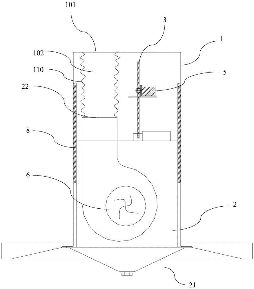
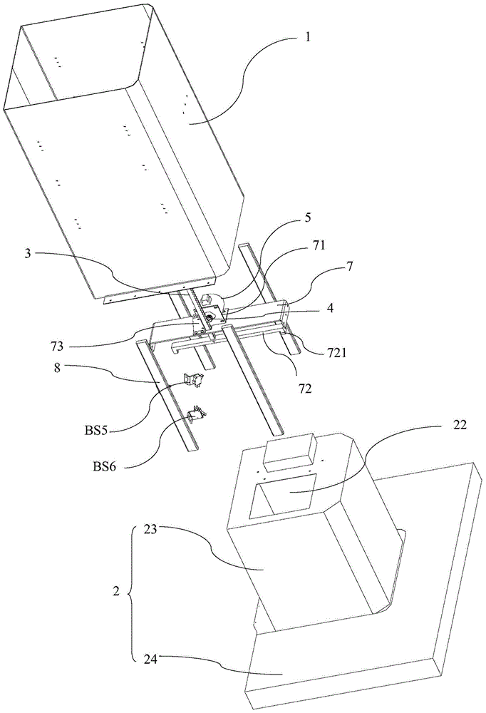
A movable negative-pressure purification device, comprising a casing (1), an air duct (2) installed in the casing and able to move up and down relative to the casing, and a drive structure for driving the air duct (2) to move up and down; the bottom end of the air duct is provided with a negative-pressure suction port (21) forming a negative-pressure area and used to draw in waste gas and smoke, and the top end of the air duct (2) is provided with an exhaust outlet (22); the top end of the casing (1) is provided with a discharge outlet (101) for discharging into the external environment the waste gas and smoke drawn in by negative-pressure; the casing (1) is provided with an exhaust channel (102) therein respectively communicating with the discharge outlet (101) and the exhaust outlet (22); the exhaust channel (102) is formed by a telescoping pipe (110) capable of extending and retracting as the air duct (2) moves up and down; and the drive structure is separated from the exhaust channel (102) via the telescoping pipe (110), such that the waste gas and smoke are directly discharged to the external environment via the exhaust channel, and will not diffuse into the casing, thus preventing the drive structure from being polluted or corroded, and reducing the frequency of maintenance and replacement. Also disclosed is a movable negative-pressure purification system.

Description

technical field [0001] The invention relates to a device and a system for purifying indoor air by sucking various waste gas smog or dust in industrial production sites and cooking workshops. Background technique [0002] In the prior art, for the negative pressure purification devices used in laboratories and factories to discharge exhaust gas and smoke, the blower is far away from the work surface, so that the effect of sucking exhaust gas and smoke is poor, and the exhaust smoke that is not discharged stays in the operating area. In the space, it is very unfavorable to human health. In the prior art, the air cylinder of the negative pressure purification device is also designed to move up and down, and then it can be close to the work surface to improve the efficiency of sucking exhaust gas smoke, such as the Chinese utility model patent (patent application No. 201220080687.0) with a movable head The range hood and the blower can move up and down, but the smoke will sprea...

Claims


Application Information

Patent Timeline
Patent Type & Authority Patents(China)
IPC IPC(8): B08B15/04F24C15/20
CPCF24C15/20
Inventor 庄明
Owner 庄明
Learn More