
Full-automatic assembly machine for fiber splicing thermal shrinkage protective casings

A technology for protective sleeve and optical fiber fusion, which is applied in the fields of mechanical automation and machinery, and can solve problems such as low production efficiency, difficulty in splicing fiber protection tubes, and reducing mechanical strength.

Active Publication Date: 2015-02-25
HEBEI XINGLONG ELEVATORING EQUIP CO LTD
View PDF6 Cites 17 Cited by
  • Summary
  • Abstract
  • Description
  • Claims
  • Application Information

AI Technical Summary

Problems solved by technology

The removed optical fiber protective layer has a certain mechanical strength, which reduces the mechanical strength of the optical fiber connection because there is no optical fiber protective layer. Therefore, the optical fiber fusion heat shrinkable protective sleeve with steel needles came into being.
However, traditional optical fiber fusion splicing heat-shrinkable protective sleeves are assembled manually, because the outer diameter of the heat-shrinkable tube in the inner layer of this optical fiber fusion-spliced ​​heat-shrinkable protective sleeve is not much different from the inner diameter of the outer heat-shrinkable tube. There is a steel needle to enhance the mechanical strength between the heat-melt tube and the heat-shrinkable tube, so it is difficult to manually assemble this kind of fusion fiber protection tube, and the production efficiency is also very low

Method used


Image

  • Full-automatic assembly machine for fiber splicing thermal shrinkage protective casings
  • Full-automatic assembly machine for fiber splicing thermal shrinkage protective casings
  • Full-automatic assembly machine for fiber splicing thermal shrinkage protective casings

Examples


Embodiment Construction

[0032] The present invention will be further described below in conjunction with the accompanying drawings and specific embodiments.

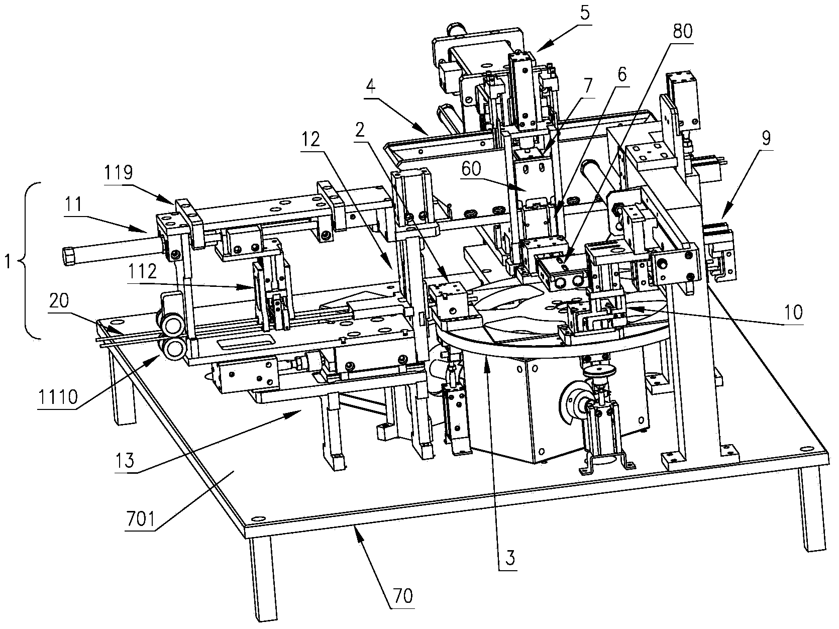
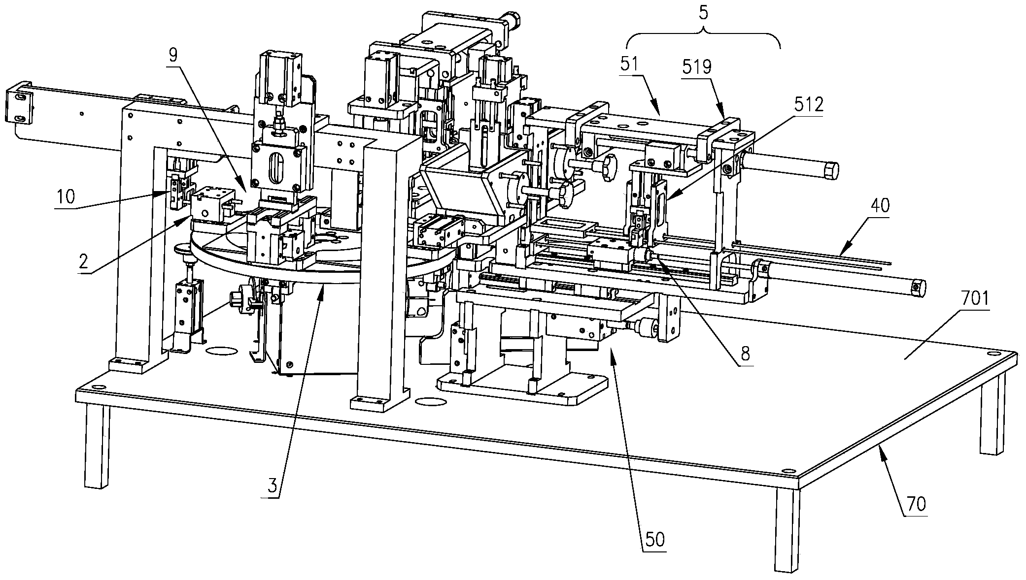
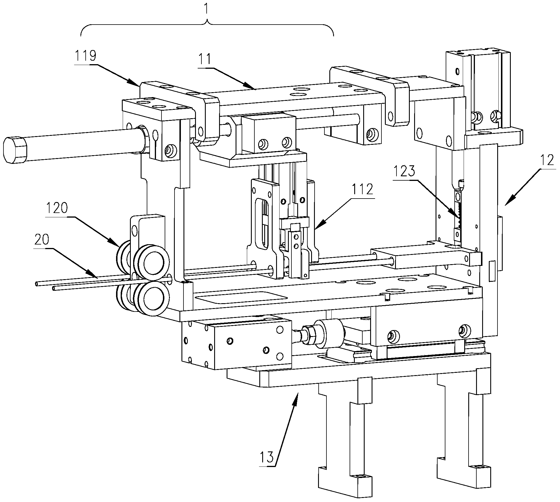
[0033] Such as figure 1 and figure 2 As shown, the fully automatic assembly machine for optical fiber fusion splicing heat-shrinkable protective sleeve of the present invention includes a heat-shrinkable tube automatic conveying and cutting device 1, a heat-shrinkable tube clamping device 2, a turntable assembly 3, a steel needle automatic material-distributing conveying device 4, Hot-melt pipe automatic conveying and cutting device 5 , workpiece carrier 6 , pushing device 7 , assembling device 8 , blanching device 9 , retrieving device 10 and frame 70 .

[0034] Specifically, such as figure 1 , figure 2 and Figure 22 As shown, the rack 70 is provided with a rack deck 701 . The workpiece carrier 6 is a carrier for accommodating the steel needle 30 and the hot-melt tube 40 before assembly. It is provided with two U-shaped grooves 61. The...


PUM


Abstract

The invention discloses a full-automatic assembly machine for fiber splicing thermal shrinkage protective casings. The full-automatic assembly machine comprises a rotary disc assembly. The rotary disc assembly is provided with four identical graduations. Thermal shrinkage pipe clamping devices are installed at the identical graduations respectively. A workpiece carrier base is provided with a U-shaped groove. An automatic thermal shrinkage pipe conveying and cutting device conveys a thermal shrinkage pipe of fixed length to the thermal shrinkage pipe clamping devices to be clamped and cut off, the rotary disc assembly rotates to the next identical graduation position, an automatic steel pin separating and conveying device conveys a steel pin to the U-shaped groove, the automatic thermal shrinkage pipe conveying and cutting device conveys a hot melting pipe of fixed length to the U-shaped groove to be cut off, a pushing device pushes the hot melting pipe to the steel pin, an assembly device pushes the steel pin and the hot melting pipe into the thermal shrinkage pipe at the same time, and the rotary disc assembly rotates to the next identical graduation position; a hot ironing device carries out hot ironing on the two ends of the thermal shrinkage pipe, so that the thermal shrinkage pipe shrinks to wrap the steel pin and the hot melting pipe, and then rotary disc assembly rotates to the next identical graduation position; a fetching device fetches a well assembled finished product, and then the rotary disc assembly rotates to the initial position.

Description

technical field [0001] The invention relates to the field of machinery, in particular to the field of mechanical automation, in particular to a fully automatic assembly machine for heat-shrinkable protective sleeves for optical fiber fusion splicing. Background technique [0002] When performing fusion splicing on the optical fiber, it is necessary to remove the protective layer at the connecting end of the optical fiber to expose the optical fiber for fusion splicing. The removed optical fiber protective layer has a certain mechanical strength, which reduces the mechanical strength of the optical fiber connection due to the absence of the optical fiber protective layer. Therefore, the optical fiber fusion heat-shrinkable protective sleeve with steel needles came into being. However, traditional optical fiber fusion splicing heat-shrinkable protective sleeves are assembled manually, because the outer diameter of the heat-shrinkable tube in the inner layer of this optical fib...

Claims


Application Information

Patent Timeline
Patent Type & Authority Applications(China)
IPC IPC(8): B23P21/00G02B6/255
CPCB23P21/006G02B6/2553
Inventor 李平
Owner HEBEI XINGLONG ELEVATORING EQUIP CO LTD
Learn More