Fiber fabric supported mean-speed air pipe system

A technology of fiber fabric and air duct, which is applied in the field of fiber fabric supported uniform velocity air duct system, which can solve the problems of poor cooling effect in the end area of ​​the air duct, achieve stable operation, change the infiltration air volume, and reduce the pressure difference

Inactive Publication Date: 2015-02-25
DURKEESOX WUHAN AIR DISTRIBUTION SYST
8 Cites 5 Cited by

AI-Extracted Technical Summary

Problems solved by technology

[0004] The head and tail are equal-diameter round pipes. The wind speed in the pipe changes uniformly and linearly under the working state, and the average wind speed along the way is 1/2 of the inle...

Abstract

The invention relates to a fiber fabric supported mean-speed air pipe system. An air pipe unit of the air pipe system is a taper air pipe. The pipe diameter of the air pipe unit gradually decreases from the inlet to the tail end along the process. The air pipe system comprises hanging hooks, tension rings, a hanging steel rope and a tail end support. Air pipes are hung and fixed to the hanging steel rope through the hanging hooks. The tail ends of the air pipes are fixed to the tail end support through the steel rope via stretching. The tension rings used for supporting are installed in the air pipes. The pipe diameter of the air pipes is adjusted along the process, the taper is adjusted, and then the air conveying character in the air pipes is changed along the process. Meanwhile, the air pipe system is provided with a supporting structure and is circular under the non-working state.

Application Domain

Pipe supportsFlexible pipes

Technology Topic

FiberArchitectural engineering +1

Image

  • Fiber fabric supported mean-speed air pipe system

Examples

  • Experimental program(1)

Example Embodiment

[0024] In order to make the object, technical solution and advantages of the present invention more clear, the present invention will be further described in detail below in conjunction with the examples. It should be understood that the specific embodiments described here are only used to explain the present invention, not to limit the present invention.
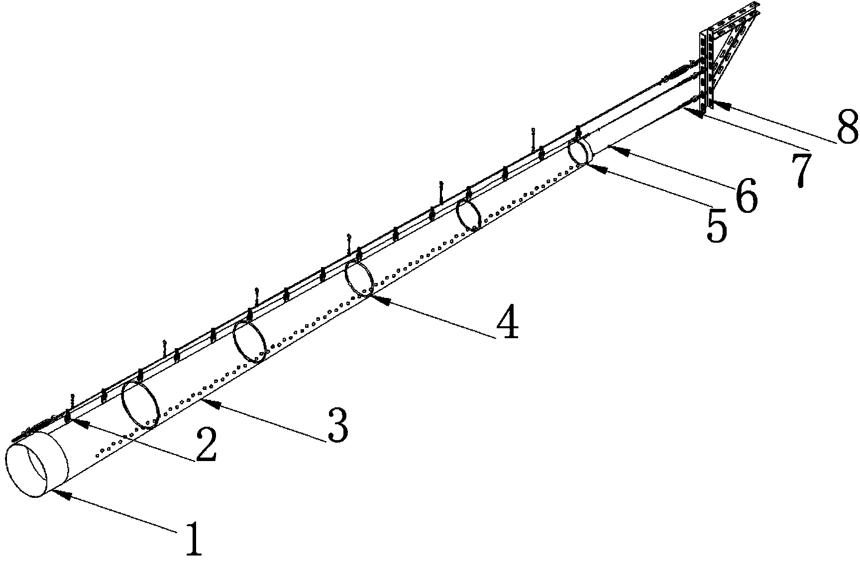
[0025] like figure 1 As shown, a supported uniform velocity duct system with different pipe diameters and tension rings along the way is suspended by steel ropes, and the tension ring at the end of the duct is stretched on the end bracket by steel ropes. The branch system consists of air duct inlet 1, air duct end 5, air duct unit 3, and tension ring 4. The inner wall of the air duct unit 3 is compounded with interlayers in the circumferential direction, and a number of closed rings 4 for support are butted and inserted in the interlayers. The closed rings are polyester fiber rod rings inserted through plastic joints at the joints. Multiple closed rings are set at intervals of 1 to 2 meters. Polyester fiber rods are made of flame-retardant lightweight materials (density less than 100g/m), and different pipe diameters correspond to different specifications (about 3mm-8mm). The tension is (0.5N-10N). The air duct unit 3 is a tapered air duct, and the air duct from the inlet to the end has successively decreasing pipe diameters along the way. The diameter of the air duct can be designed as a uniform decreasing diameter, and can also be designed as a non-uniform decreasing diameter according to the needs, making it a fiber fabric supporting uniform velocity air duct with a specific taper or variable taper. When the diameter of the air duct is uniformly decreasing, the air duct unit is a conical air duct, and the cone angle θ ranges from 0
[0026] The air duct unit of the air duct system is a fiber fabric air duct unit, or a composite fiber fabric air duct unit. The composite fiber fabric air duct unit includes an aluminum foil layer, an insulation layer and a fiber fabric layer from the inside to the outside; the aluminum foil layer, The insulation layer and the fiber fabric layer are bonded and compounded by flame-retardant glue; zippers are sewn at both ends of the air duct unit; the insulation layer is a flexible insulation layer, and the insulation layer is made of polyethylene foam material.
[0027] When the air duct layout is required, the air duct system includes an air duct unit, an air duct elbow or an air duct tee or an air duct variable diameter and an air duct end for connecting the air duct unit; Zipper, the air duct units are connected by zippers; the air duct tee or air duct elbow or air duct variable diameter is connected to the inner side of the butt ends of two adjacent air duct units to be connected.
[0028] like figure 1 As shown, the air duct suspension hook is sewn on the surface of the air duct unit of the air duct system, and the suspension hooks are evenly distributed in rows along the axial direction of the air duct unit; there is a stretching hook outside the tension ring at the end position of the air duct; The ring is connected to the quick tensioner 6 through the stretching hook, and the quick tensioner is fixed on the side bracket 8 by the eyebolt 7 . All fiber fabric air ducts are tightened by the tension adjustment of the quick tensioner; when there is no ventilation, the air ducts maintain their shape by the circumferential tension of the closed ring and the tensile force at both ends of the air ducts, and the moment of ventilation, a momentary Static pressure, but because the surface of the air duct itself has a certain tension, it will not produce noise and vibration, thus achieving the effect of noise reduction and vibration reduction.
[0029] It should be understood that those skilled in the art can make improvements or changes based on the above description, and all these improvements and changes should belong to the protection scope of the appended claims of the present invention.

PUM

PropertyMeasurementUnit
Cone angle0.0 ~ 45.0deg

Description & Claims & Application Information

We can also present the details of the Description, Claims and Application information to help users get a comprehensive understanding of the technical details of the patent, such as background art, summary of invention, brief description of drawings, description of embodiments, and other original content. On the other hand, users can also determine the specific scope of protection of the technology through the list of claims; as well as understand the changes in the life cycle of the technology with the presentation of the patent timeline. Login to view more.

Similar technology patents

Group matching method for reducing dynamic voltage difference of power type lithium battery pack

PendingCN113067045AReduce differential pressureImprove capacity conversion rate
Owner:江西安驰新能源科技有限公司

Melt spinning cartridge

InactiveCN103521000AReduce differential pressureStrong dirt holding capacity
Owner:高永凤

Rotary objective table for multi-station precise operation, and control method

ActiveCN108696182AStable dynamic characteristicsrun smoothly
Owner:NORTHEASTERN UNIV

Multifunctional combined type sole massage mechanism

PendingCN106943299ASimple structurerun smoothly
Owner:SHANGHAI RONGTAI FITNESS TECH DEV CO LTD

Gateway power supply circuit, gateway integration device and gateway power supply method for elevator

PendingCN112531872AReduce differential pressureReduce pressure drop loss
Owner:HANGZHOU OPTIMAX TECH

Control method and device for air conditioning system

ActiveCN110131848ABalanced air intake and exhaust air volumeReduce differential pressure
Owner:QINGDAO HAIER AIR CONDITIONER GENERAL CORP LTD +1

Integrated treatment method of p-(beta-sulfatoethylsulfonyl)aniline production wastewater

InactiveCN105347624Arun smoothlyStrong anti-toxicity
Owner:XINXIANG HUIFENG DYEING & CHEM CO LTD

Classification and recommendation of technical efficacy words

  • run smoothly
  • Reduce differential pressure

Insulator cleaning robot

ActiveCN104438164Arun smoothlyreduce wear
Owner:STATE GRID INTELLIGENCE TECH CO LTD

Full-automatic packing method

Owner:广东邦天智能制造有限公司

One-axle multi-cylinder multi-dimensional ball hammer type micro-nano high-energy ball mill

InactiveCN104117411AImprove production and efficiencyrun smoothly
Owner:深圳市来源新材料科技有限公司

Melt spinning cartridge

InactiveCN103521000AReduce differential pressureStrong dirt holding capacity
Owner:高永凤

Group matching method for reducing dynamic voltage difference of power type lithium battery pack

PendingCN113067045AReduce differential pressureImprove capacity conversion rate
Owner:江西安驰新能源科技有限公司

Control method and device for air conditioning system

ActiveCN110131848ABalanced air intake and exhaust air volumeReduce differential pressure
Owner:QINGDAO HAIER AIR CONDITIONER GENERAL CORP LTD +1

Gateway power supply circuit, gateway integration device and gateway power supply method for elevator

PendingCN112531872AReduce differential pressureReduce pressure drop loss
Owner:HANGZHOU OPTIMAX TECH
Why Eureka
Try Eureka