Interference measurement method for refractive index of lens

A technology of interferometric measurement and refractive index, which is applied in the field of optical measurement to achieve the effect of fast measurement speed and convenient adjustment

Inactive Publication Date: 2015-02-25
INST OF OPTICS & ELECTRONICS - CHINESE ACAD OF SCI
View PDF5 Cites 4 Cited by
  • Summary
  • Abstract
  • Description
  • Claims
  • Application Information

AI Technical Summary

Problems solved by technology

[0005] The purpose of the present invention is to solve the problem of non-contact high-precision measurement of t...

Method used


Image

  • Interference measurement method for refractive index of lens
  • Interference measurement method for refractive index of lens
  • Interference measurement method for refractive index of lens

Examples


Embodiment 1

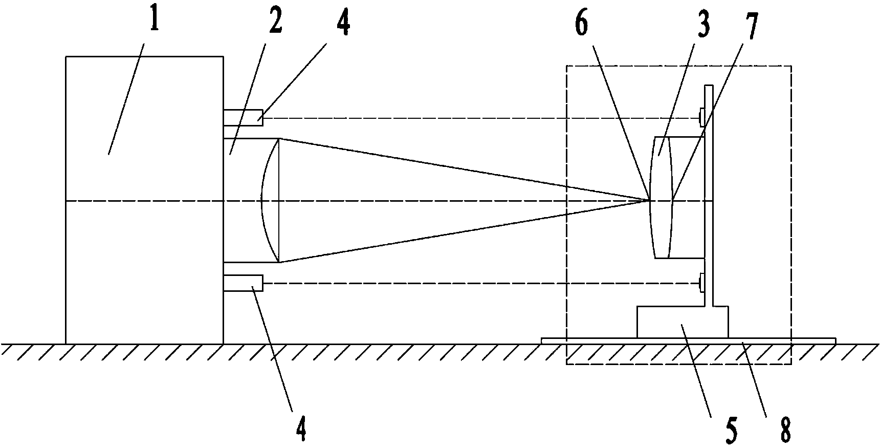
[0048] Such as figure 1 , figure 2 As shown, the concave lens refractive index interferometry method, the measurement steps are:

[0049] First, the concave lens to be measured is installed on the five-dimensional adjustment frame 5, and then the five-dimensional adjustment frame 5 is installed on the guide rail 8, and the two-way distance measuring interferometer 4 is symmetrically installed between the five-dimensional adjustment frame 5 and the interferometer 1 , adjust the measurement beam of the ranging interferometer 4 to be parallel to the guide rail 8 . The relevant parameters are known, which mainly include the radius of curvature r=423.684mm of the front surface 6 of the concave lens to be measured, the refractive index of air n 0 =1 and the center thickness of the measured concave lens 3 is d=30.6mm.

[0050] Then, turn on the interferometer 1, adjust the measured concave lens 3 to be coaxial with the standard objective lens 2, and adjust the standard objective ...

Embodiment 2

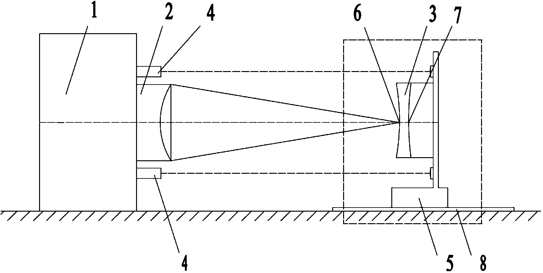
[0058] Such as figure 1 , Figure 4 As shown, the plane lens refractive index interferometry method, the measurement steps are:

[0059] First, install the measured plane lens on the five-dimensional adjustment frame 5, then install the five-dimensional adjustment frame 5 on the guide rail 8, and install two-way distance measuring interferometers symmetrically between the five-dimensional adjustment frame 5 and the interferometer 1 4. Adjust the measurement beam of the ranging interferometer 4 to be parallel to the guide rail. The relevant parameters are known, which mainly include the refractive index of air n 0 =1 and the center thickness of the measured plane lens 3 d=17.04mm.

[0060] Then, open the interferometer 1; Adjust the measured plane lens 3 to be coaxial with the standard objective lens 2, and adjust the standard objective lens 2 and the measured plane lens 3 to be perpendicular to the incident parallel light beam; known standard objective lens 2 aperture D=100...


PUM


Abstract

The invention discloses an interference measurement method for the refractive index of a lens. The method comprises the following steps that the lens to be measured is moved, so that parallel beams emitted by an interferometer converge on the surface of the lens to be measured after passing through a normal lens; then, distance measurement and surface shape error compensation are conducted through two distance measurement interferometers, two-time locating position coordinates of the vertexes of the front surface and the back surface of the lens to be measured are obtained, and the refractive index of the lens is worked out through a ray tracing formula. Measuring equipment used in the method comprises the interferometers, the normal objective lens, a laser range finder, a five-dimensional adjusting rack and a movable guide rail. The normal objective lens and the lens to be measured are sequentially placed in the direction of emergent rays of an interferometer light source. The lens to be measured is fixed to the five-dimensional adjusting rack and can move on the guide rail. Locating and position compensation are conducted on the surfaces of the lens according to an interference method, and non-contact measurement of the refractive index of the lens is achieved.

Description

technical field [0001] The invention belongs to the technical field of optical measurement, and in particular relates to a lens refractive index interferometric measurement method. Background technique [0002] The lens is the most commonly used optical element in the optical system, and the refractive index of the lens is one of the important physical parameters of the optical element, which has a great influence on the quality of the optical system. For some demanding systems, the refractive index of the optical materials used must be accurately measured. [0003] At present, there are few methods about the refractive index of lenses. There are two main types of measuring the refractive index of glass: goniometric method and interferometric method. Goniometric methods include minimum deflection method, V prism method and self-collimation method. The above method has high precision, but it needs to process the element into a specific shape or coat a specific reflective f...

Claims


Application Information

Patent Timeline
IPC IPC(8): G01M11/02
Inventor 毛洁侯溪伍凡
Owner INST OF OPTICS & ELECTRONICS - CHINESE ACAD OF SCI
Why Eureka
Try Eureka