Visible light positioning system and method based on timing sequence markers

A timing marking and positioning method technology, applied in the field of LED optical communication and indoor positioning applications, can solve the problems affecting the distance estimation and positioning results, light source layout restrictions, hardware complexity, etc., to achieve improved system robustness, simple system structure, The effect of reducing the influence of single measurement deviation

Active Publication Date: 2015-02-25
WUHAN POST & TELECOMM RES INST CO LTD
View PDF5 Cites 11 Cited by
  • Summary
  • Abstract
  • Description
  • Claims
  • Application Information

AI Technical Summary

Problems solved by technology

[0004] Because in the RSS-based measurement scheme, different LEDs need to be distinguished and identified by different frequencies or transmission sequences, using different frequencies or transmission sequences for each LED will bring hardware complexity and increase costs
Since the received optical power is usually affected by factors such as the brightness of the light source, the scattering and reflection of signal light, the angle of light transmission and reception, background light interference, etc., the fluctuation of received optical power and various measurement errors will affect the distance estimation and the final positioning result
When the detection distance is short, small distance changes will lead to significant changes in received power. Therefore, the three LEDs with the shortest detection distance and the largest received power are usually selected for three-point positioning, which has certain restrictions on the placement of light sources.

Method used


Image

  • Visible light positioning system and method based on timing sequence markers
  • Visible light positioning system and method based on timing sequence markers
  • Visible light positioning system and method based on timing sequence markers

Examples


Embodiment Construction

[0025] The present invention will be described in further detail below in conjunction with the accompanying drawings and embodiments.

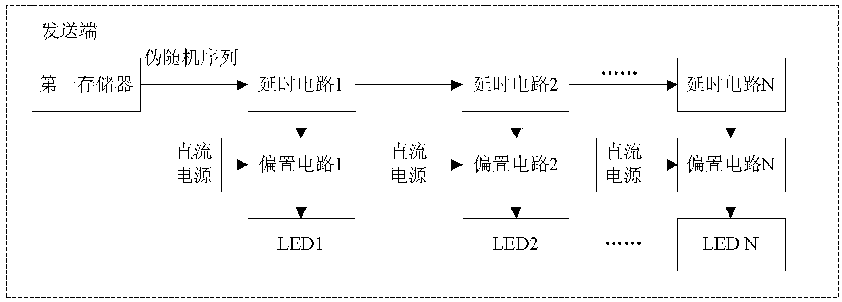
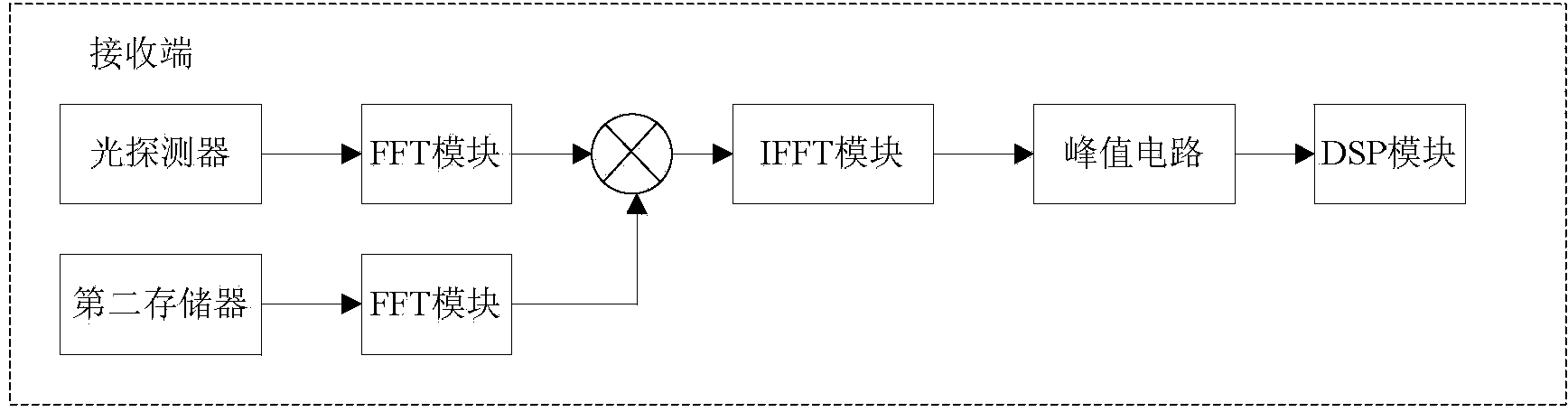
[0026] Such as figure 1 and figure 2 As shown, the timing mark-based visible light positioning system of the present invention includes a sending end and a receiving end. The sending end includes a first memory and a plurality of delay circuits arranged in series, and the number of delay circuits is at least three. Each delay circuit is correspondingly connected to a bias circuit, each bias circuit is connected to an LED, each bias circuit is also connected to a DC power supply, the first memory is used to provide a pseudo-random sequence to the delay circuit, each delay The circuit delays the received electrical signal for a certain period of time and sends it, and the bias circuit is used to drive the LED to emit signal light. The receiving end includes a photodetector and a second memory, which are connected to a multiplier after passing...


PUM


Abstract

The invention provides a visible light positioning system and method based on timing sequence markers and relates to the field of LED optical communication and indoor positioning application. A sending terminal sends pseudorandom sequences having the same content through a plurality of LEDs according to different delays; a light detector of a receiving terminal detects multiple beams of signal light simultaneously, the signal light is converted into an electrical signal, self-correlation operation is conducted on the electrical signal and the pseudorandom sequences of the sending terminal, and timing sequences and correlated peak values corresponding to the signal light from the different LEDs are determined; the correlated peak values of signals from any three different LEDs and the coordinates of the corresponding LEDs are substituted into the equation that I(theta)=F(theta)*I0, simultaneous calculation is conducted, and the coordinates (x, y, z) of the light detector are obtained. Hardware of the sending terminal and the receiving terminal is simplified effectively, and meanwhile limitations on light source distribution are reduced.

Description

technical field [0001] The invention relates to the application field of LED optical communication and indoor positioning, in particular to a visible light positioning system and method based on timing marks. Background technique [0002] LED (Lighting Emitting Diode, light-emitting diode) is called the fourth-generation lighting source or green light source. It has the advantages of energy saving, safety, and wide available spectrum. and a series of extended applications. LED-based indoor positioning is one of the application directions with great potential. Since LEDs are placed in a fixed position indoors and have a wide coverage area, the position and distance can be accurately known with each LED as a reference, and GPS-like positioning and navigation can be realized indoors. [0003] Since the LED communication system has the characteristics of optical wireless communication, LED positioning is usually based on RSS (Received Signal Power, received signal strength), AO...

Claims


Application Information

Patent Timeline
Patent Type & Authority Applications(China)
IPC IPC(8): G01S5/16
CPCG01S5/16
Inventor 刘武杨超杨奇
Owner WUHAN POST & TELECOMM RES INST CO LTD
Why Eureka
Try Eureka