
Method for Improving LED Chip Current Expansion and LED Chip

A technology of LED chips and current expansion, applied in circuits, electrical components, semiconductor devices, etc., can solve the problems of ITO coarsening current, expansion and other problems, and achieve the effect of solving the problem of easy current concentration, solving voltage rise, and preventing current accumulation

Inactive Publication Date: 2017-02-22
ENRAYTEK OPTOELECTRONICS
View PDF3 Cites 0 Cited by
  • Summary
  • Abstract
  • Description
  • Claims
  • Application Information

AI Technical Summary

Problems solved by technology

In addition, in the case of ITO thickness reduction, ITO coarsening will also cause current spreading problems

Method used


Image

  • Method for Improving LED Chip Current Expansion and LED Chip
  • Method for Improving LED Chip Current Expansion and LED Chip
  • Method for Improving LED Chip Current Expansion and LED Chip

Examples


Embodiment Construction

[0023] The method for improving LED chip current expansion and the LED chip of the present invention will be described in more detail below in conjunction with schematic diagrams, wherein a preferred embodiment of the present invention is shown. It should be understood that those skilled in the art can modify the present invention described here, and still The advantageous effects of the present invention are realized. Therefore, the following description should be understood as the broad knowledge of those skilled in the art, but not as a limitation of the present invention.

[0024] In the interest of clarity, not all features of an actual implementation are described. In the following description, well-known functions and constructions are not described in detail since they would obscure the invention with unnecessary detail. It should be appreciated that in the development of any actual embodiment, numerous implementation details must be worked out to achieve the develope...


PUM


Abstract

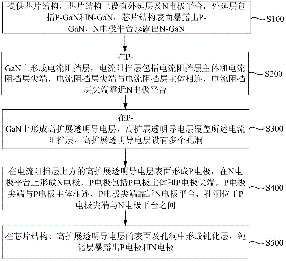
The invention provides a method for improving current expansion of an LED chip and the LED chip. Multiple holes are formed in a high-expansion transparent conductive layer, the holes are located between the tip end of a P electrode and an N electrode forming on an N electrode platform, and accordingly the problem that currents at the tip end of the P electrode are easy to collect can be solved. Current collecting is prevented, the problem that voltage rises due to expansion of the high-expansion transparent conductive layer is solved, and the voltage of the LED chip is lower.

Description

technical field [0001] The invention relates to the field of LED manufacturing, in particular to a method for increasing the current expansion of an LED chip and the LED chip. Background technique [0002] Light Emitting Diode (LED for short) is a semiconductor light-emitting device, which is composed of gallium (Ga) and arsenic (As), phosphorus (P), nitrogen (N), indium (In) compounds, using semiconductor P-N junction Made on the principle of electroluminescence. LED chips have become the first choice for a new generation of light sources due to their advantages of high brightness, low power consumption, long life, fast start-up, low power, no flicker, and not easy to cause visual fatigue. [0003] ITO (Indium Tin Oxides) is indium tin oxide. Compared with other transparent semiconductor conductive films, ITO has good chemical stability and thermal stability, and has good adhesion and pattern processing characteristics to semiconductor substrates. In the oxide conductive...

Claims


Application Information

Patent Timeline
Patent Type & Authority Patents(China)
IPC IPC(8): H01L33/14
CPCH01L33/14
Inventor 于婷婷徐慧文张宇李起鸣
Owner ENRAYTEK OPTOELECTRONICS
Learn More