Low Power Undervoltage Release

An undervoltage release and low power consumption technology, which is applied in the direction of protection against undervoltage or no voltage, can solve problems such as undervoltage release misoperation, circuit breaker false opening, and imperfection. Achieve the effect of overcoming small starting torque, avoiding harmonic interference, and broadening the use occasions

Inactive Publication Date: 2018-08-24
CHANGZHOU INST OF TECH
View PDF7 Cites 0 Cited by
  • Summary
  • Abstract
  • Description
  • Claims
  • Application Information

AI Technical Summary

Problems solved by technology

[0004] Referring to the above principles, most of the existing undervoltage releases work in the single-phase power supply mode
The integrated undervoltage release in the three-phase circuit has not yet seen more mature undervoltage release solutions and products.
[0005] Moreover, the circuit design of the existing undervoltage release is mostly simple or imperfect. In the occasions where the interference is serious, especially the circuit breaker near the intermediate frequency application occasion, the undervoltage release is often interfered by the intermediate frequency and malfunctions.
Or when the frequency of the marine generator changes, the undervoltage release will malfunction due to the frequency change
The misoperation of the undervoltage release caused the misopening of the circuit breaker

Method used


Image

  • Low Power Undervoltage Release
  • Low Power Undervoltage Release
  • Low Power Undervoltage Release

Examples


Embodiment 1

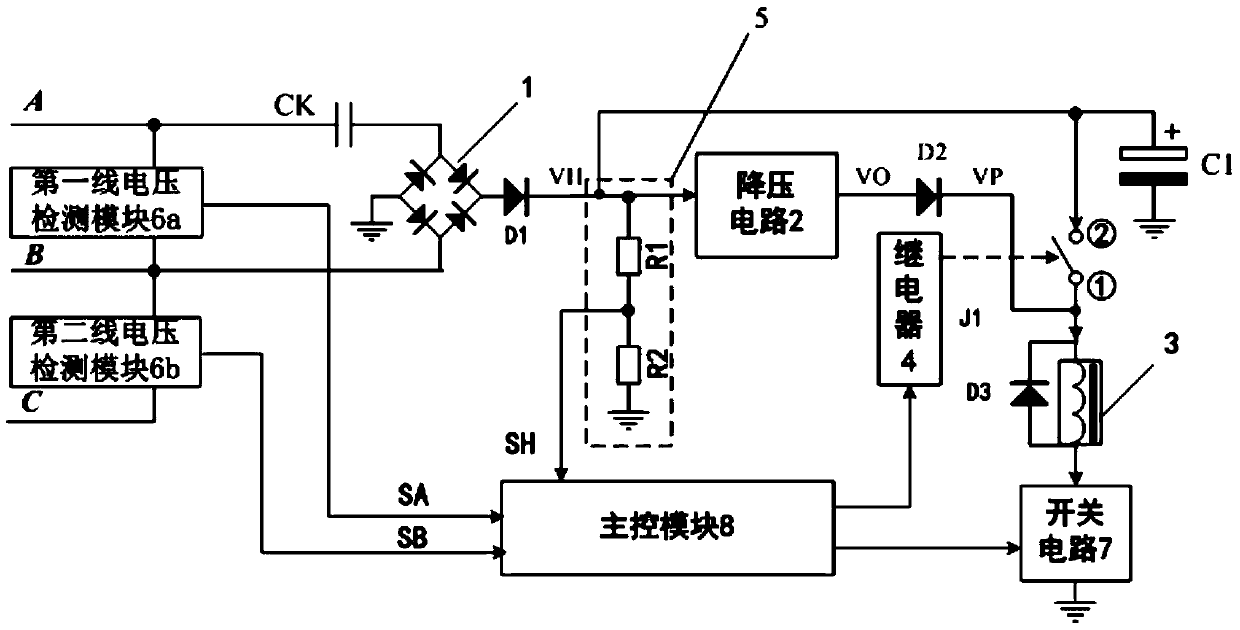
[0035] See Figure 1-2, an undervoltage release, comprising: an electromagnet coil 3, an armature controlled by the electromagnet coil 3; a rectifier circuit 1, whose input terminal is connected to any line voltage in a three-phase power supply; a step-down circuit 2, Its input terminal is connected to the positive output terminal of the rectifier circuit 1, and its output terminal is connected to the current input terminal of the electromagnet coil 3 to provide a voltage for maintaining the armature pull-in; the relay 4 has a pair of normally open contacts points are respectively connected with the output terminal of the rectifier circuit 1 and the current input terminal of the electromagnet coil 3; the switch circuit 7, the current output terminal of the electromagnet coil 3 is connected with the input terminal of the switch circuit 7; the line voltage The detection module is set at the output end of the three-phase power supply and is used to detect at least two sets of lin...

Embodiment 2

[0044] See Figure 1-3 , on the basis of Example 1, the implementation of the main part of the undervoltage release is described.

[0045] After the alternating current passes through the rectifying circuit 1, a full-wave pulsating voltage VH is formed to charge the strong start-up capacitor C1. The VH voltage is stepped down by the step-down circuit 2 to supply power to the main control module 8, and at the same time provide power to the relay 4 and the switch circuit 2. The voltage VO formed by the step-down circuit 2 is isolated by the diode D2 and the voltage VP is obtained. The electromagnet coil 3 is powered. The resistors R1 and R2 form a sampling circuit of VH, and the sampling signal SH is sent to the main control module 8 .

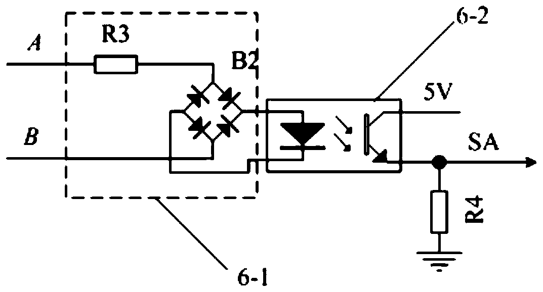
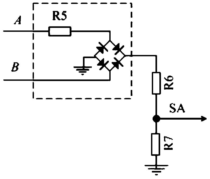
[0046] Wherein the line voltage detection module includes: a first line voltage detection module 6a and a second line voltage detection module 6b respectively connected between any two line voltages; The output voltage SA of the first-line vo...

Embodiment 3

[0054] See Figure 1-4 , on the basis of Embodiment 1-2, taking 330V voltage and the main control module 8 using a single-chip microcomputer circuit as an example, it is illustrated that the anti-harmonic and multi-frequency undervoltage are suitable for the implementation of the main part of the undervoltage release of the three-phase power supply Way.

[0055] The line voltage is connected to the two input ends of the rectification circuit 1 after EMC bidirectional filtering. The positive end of the rectification circuit 1 is defined as (VH), and the negative end is grounded (GND).

[0056] After power-on, the rectifier circuit 1 rectifies the AC voltage into a DC pulsating voltage SP, charges the strong start-up capacitor C1 through the isolation diode D1, and the charging voltage VH is equal to the input AC voltage times (80% effective value, approximately equal to 430V). The charging voltage has a voltage sampling circuit 5 composed of R1 and R2 in series, and the pro...


PUM


Abstract

The invention relates to a low-power-consumption undervoltage tripper. The low-power-consumption undervoltage tripper comprises an electromagnet coil, an armature, a rectifying circuit, a step-down circuit, a relay, line voltage detection modules, a sampling circuit and a master control module. A nominal voltage Ue and a forced start voltage value are stored in the master control module, and the master control module is used for collecting the output voltage and the voltage period of each line voltage detection module so as to work out the effective value of each line voltage of a three-phase supply; when the effective values of all the line voltages of the three-phase supply reach 80% of the nominal voltage Ue at the same time and the sampling voltage of the sampling circuit reaches the forced start voltage value, the master control module controls a normally open contact to be closed and then controls a switching circuit to be closed, and after the armature is attracted, the master control module controls the normally open contact to be opened; if the effective value of any line voltage is lower than 50% of the nominal voltage Ue, the master control module controls the switching circuit to be opened.

Description

[0001] This application is a divisional application of the invention patent application with the application number 201210227665.7, the application date is July 2, 2012, and the invention name is "an undervoltage release device with low power consumption and suitable for three-phase power supply". technical field [0002] The invention relates to an undervoltage release device with low power consumption and suitable for three-phase power supply. Background technique [0003] The undervoltage release is one of the important components of circuit breakers, especially frame circuit breakers. The undervoltage release is a release that makes the circuit breaker disconnect with or without delay when its terminal voltage drops to a certain range. When the power supply voltage drops (even slowly) to the rated operating Within the range of 70% to 35% of the voltage, the undervoltage release should act (the coil of the release is de-energized, and the movable armature in the coil is p...

Claims


Application Information

Patent Timeline
Patent Type & Authority Patents(China)
IPC IPC(8): H02H3/24
Inventor 徐磊吴志祥高波
Owner CHANGZHOU INST OF TECH
Why Eureka
Try Eureka