Contrast pattern application for three-dimensional imaging

A three-dimensional imaging and patterning technology, which is applied in the application, nebulizer for treatment, medical equipment, etc., can solve problems such as time-consuming and troublesome patients

Inactive Publication Date: 2015-02-25
ARGES IMAGING
View PDF13 Cites 5 Cited by
  • Summary
  • Abstract
  • Description
  • Claims
  • Application Information

AI Technical Summary

Problems solved by technology

This can be especially troublesome for patients with "cold sensitive" teeth
A...

Method used


Image

  • Contrast pattern application for three-dimensional imaging
  • Contrast pattern application for three-dimensional imaging
  • Contrast pattern application for three-dimensional imaging

Examples


example 1

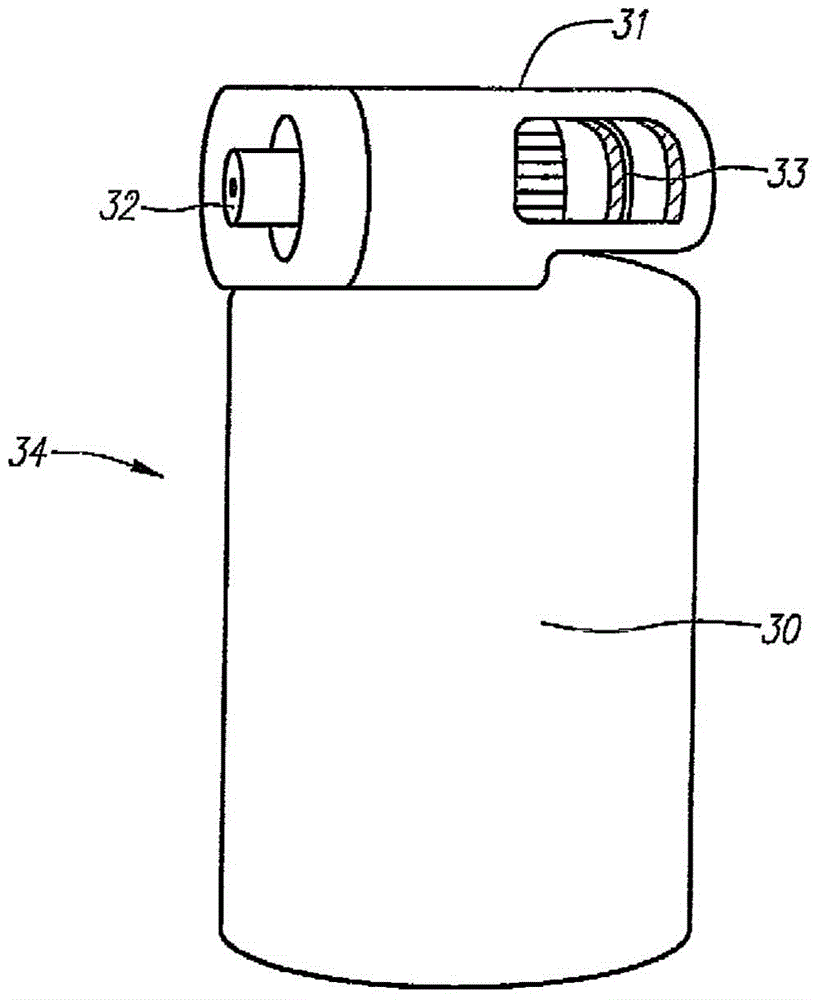
[0040] In this example, the composition was applied as a spray and HFC 227ea was used as the propellant. Table 1 shows each component constituting the composition in percentage.

[0041] Table 1

[0042]

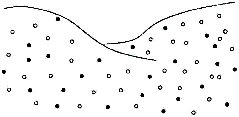
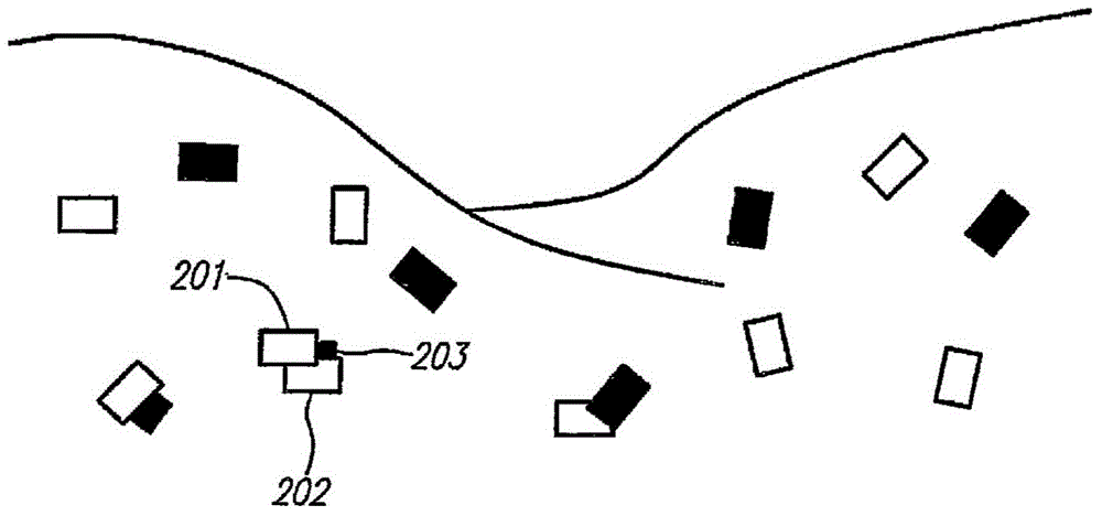
[0043] Titanium dioxide spherical particles were used as white reference marks, while glassy (glassy) carbon spherical particles were used as black reference marks. The adhesive used to bond these particles to the teeth was PVP (also known as kollidon 30). PVP is generally not soluble in Zephex 227ea, so a vehicle solvent (co-solvent) was used, which in this example was denatured alcohol (SBA) 40B. PVP is advantageous because it is soluble in alcohol without water. It was found that, in this example, the ratio of the minimum amount of PVP relative to the amount of white and black particles to provide adequate adhesion of the particles to the teeth was about 1:8.75. Thus, in applications requiring relatively more or fewer particles for imaging, the amount of PVP can ...


PUM


Abstract

Provided herein are compositions for applying a reference marker pattern or grid to the surface of an object to be imaged three-dimensionally. These compositions can be quick drying for ease of use. Methods of use of the compositions are also provided as well as devices and kits for the application of the compositions.

Description

technical field [0001] The subject matter described herein relates to apparatus for applying contrasting patterns on the surface of an object to be viewed and rendered by a three-dimensional imaging system or platform, as well as compositions bearing contrasting patterns and methods of use thereof. Background technique [0002] There are several conventional platforms for collecting two-dimensional image data of a subject's (or object's) surface and using that two-dimensional data to render (or otherwise represent) the object as a three-dimensional computer model. Most of these systems use electromagnetic radiation in the form of visible wavelengths to illuminate the surface of an object so that the reflections can then be received by an appropriate sensor or camera and placed into an electrical format. These platforms have sophisticated hardware and software that process the received information in such a way that the collected two-dimensional information can be used to ren...

Claims


Application Information

Patent Timeline
IPC IPC(8): C09D5/02A61K6/02C09D7/12A61C13/00C09K3/30A61C9/00C08K3/22A61K6/90C09D7/61C09D7/63
CPCC09D5/021A61C9/0053A61K6/002A61C9/006C08K2003/2241C09K3/30C09D7/1216C09D7/61A61K6/25A61C13/0004A61C2201/005B05B11/0037C09D7/63A61K6/80A61K6/90A61K47/02A61K47/06A61K47/10A61K47/32A61B2090/395A61M11/02A61M31/005C09D5/004C09D139/06
Inventor J.卢D.利卡塔
Owner ARGES IMAGING
Why Eureka
Try Eureka