Clamping hoop curved tooling and clamping hoop U-shaped forming mold

A technology for forming molds and clamps, applied in the directions of forming tools, manufacturing tools, feeding devices, etc., can solve the problems of inaccurate bending radius, time-consuming processing, and troublesome processing and use, so as to improve processing efficiency and processing quality. , Guarantee position accuracy and machining accuracy, avoid the effect of left and right offset

Inactive Publication Date: 2015-03-04
河南航天精工制造有限公司
View PDF6 Cites 2 Cited by
  • Summary
  • Abstract
  • Description
  • Claims
  • Application Information

AI Technical Summary

Problems solved by technology

In the manufacturing process of the aircraft, many small and light connecting parts need to be used. There is a clamp such as Figure 1-2 As shown, it needs to be widely used in the manufacturing process of aircraft. However, the production of this kind of clamp is generally processed by hand light tools, which is time-consuming and has low production efficiency. At the same time, the clamp produced by hand has a lot of precision. Can not meet the requirements, increasing the scrap rate
[0003] like image 3 Shown is the clamp blank required for processing the clamp. The clamp blank 100 is composed of four parts, including the clamp head 101 at the front end, the clamp double ears 102 including the left and right ears, and the clamp neck 103 and the clamp tail 104 located at the rear end, the processing process of the clamp mainly includes three processes, the first process is to bend the ears 102 of the clamp and process the first blank, the structure of the first blank is as follows Figure 4 As shown, the second process is to bend the clamp neck 103 and process it into a second green body, the structure of the second green body is as follows Figure 5 As shown, the third process is to flatten the clamp tail 104 and process it into a finished clamp. The existing second process is generally directly bent by hand, which often has inaccurate bending radius and clamp The parallelism between the head and the tail of the clamp does not meet the requirements, which brings great troubles to subsequent processing and use.

Method used


Image

  • Clamping hoop curved tooling and clamping hoop U-shaped forming mold
  • Clamping hoop curved tooling and clamping hoop U-shaped forming mold
  • Clamping hoop curved tooling and clamping hoop U-shaped forming mold

Examples


Embodiment Construction

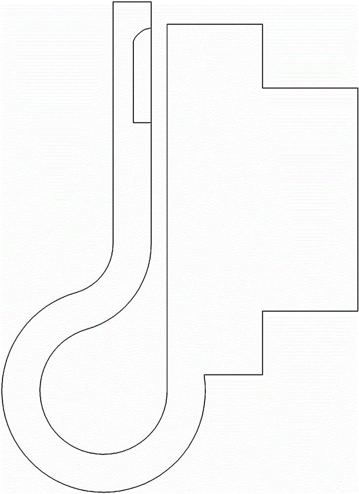
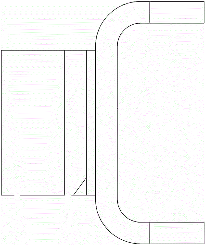
[0033] Embodiment of a kind of hoop bending tooling of the present invention: as Figure 6-19 As shown, the clamp bending tooling includes three sets of molding dies for sequentially completing the three processing steps, and the three sets of molding dies include upper and lower dies, as shown in Figure 6-9 Shown is the double lug forming tool used to process the first process, such as Figure 10-14 Shown is the clamp U-shape forming die used for processing the second process, such as Figure 15-19 Shown is the hoop arc forming mold for processing the third process. Of course, this embodiment provides a double-ear forming mold for processing the first process and a hoop arc forming mold for processing the third process. , in other embodiments, the first process and the third process can be replaced by existing manual processing.

[0034] The following is a detailed description of the three sets of molds in turn according to the drawings:

[0035] like Figure 6-7 As show...


PUM


Abstract

The invention provides a clamping hoop curved tooling and a clamping hoop U-shaped forming mold. The U-shaped forming mold comprises a second upper pressing mold and a second lower pressing mold; the second lower pressing mold is provided with a second forming groove which is used for matching with a curving radius of a neck part of a clamping hoop and extends leftwards and rightwards; the second lower pressing mold is also provided with a limiting structure which is used for stopping and limiting a first blank body in the front-and-back direction to determine a pressing and forming position of the neck part of the clamping hoop; the second upper pressing mold is provided with a second pressing head which is as same as the curving radius of the neck part of the clamping hoop and matches with the second forming groove. The limiting structure and the second forming groove of the clamping hoop U-shaped forming mold and the can determine the curving position of the neck part of the clamping hoop on the basis of ensuring the curving radius of the neck part of the clamping hoop, so that the position precision and processing precision of the clamping hoop are ensured, and the processing efficiency and the processing quality are increased greatly.

Description

Technical field [0001] The present invention involves molding molds, especially a type of card -shaped tooling and card -hoe U -shaped molding mold. Background technique [0002] With the rapid development of the aerospace industry, the level of manufacturing technology of aircraft has improved greatly.During the manufacturing process of the aircraft, many small and light weight connection parts need to be used. Figure 1-2 It is shown that in the process of manufacturing and processing of the aircraft, a large amount of use is needed. However, the production of this card hoop is generally used by handmade light tools for processing. The processing time is consuming and the production efficiency is low.It cannot meet the requirements and improve the waste rate. [0003] like image 3 It is shown in the card hoop body required for the processing card hoop. The card hoop billet 100 consists of four parts, including the front -end card hoop head 101, including the stuck binocular ears...

Claims


Application Information

Patent Timeline
Patent Type & Authority Applications(China)
IPC IPC(8): B21D37/10B21D37/12B21D43/26B21D45/04
CPCB21D37/10B21D37/12B21D43/26B21D45/04
Inventor 叶瑞
Owner 河南航天精工制造有限公司
Why Eureka
Try Eureka