
Multi-directional die forging process testing device

A process test, multi-directional die forging technology, applied in forging/press/hammer devices, driving devices of forging presses, manufacturing tools, etc., can solve problems affecting the machining accuracy of multi-directional die forging devices, uneven horizontal force Forging and other problems cannot be used to achieve the effect of improving equipment production efficiency and ensuring die forging accuracy

Inactive Publication Date: 2015-03-04
YANGZHOU JIANGDU YONGJIAN
View PDF0 Cites 9 Cited by
  • Summary
  • Abstract
  • Description
  • Claims
  • Application Information

AI Technical Summary

Problems solved by technology

Therefore, in actual production, the horizontal cylinder only plays the role of mold clamping, and cannot be used for forging in the horizontal direction.
At the same time, when multi-directional die forging is performed on large forgings, the problem of uneven force in the horizontal direction may also occur, which seriously affects the processing accuracy of the multi-directional die forging device

Method used


Image

  • Multi-directional die forging process testing device
  • Multi-directional die forging process testing device
  • Multi-directional die forging process testing device

Examples


Embodiment Construction

[0016] Specific embodiments of the present invention are described below with reference to the accompanying drawings.

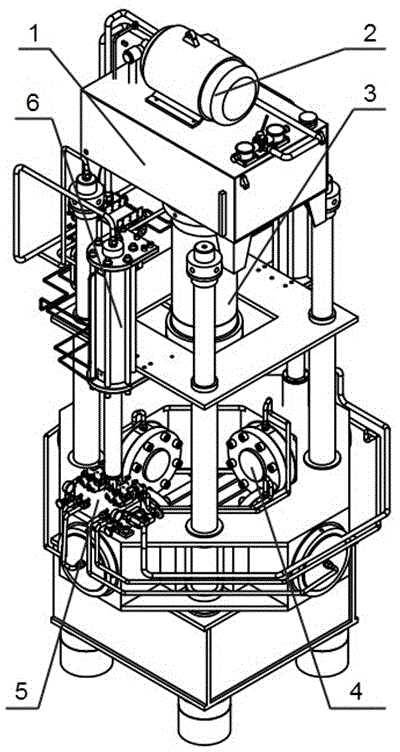
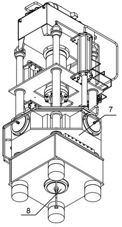
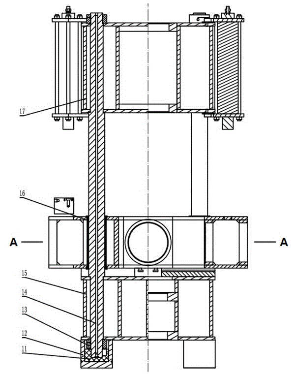
[0017] refer to figure 1 -4. The overall structure of the multi-directional die forging process test device of the present invention is described below:

[0018] The multi-directional die forging process test device includes frame-type main frame (1), hydraulic pump station (2), upper main pressure cylinder (3), four side cylinders (4), valve group (5), two lifting cylinders ( 6), moving beam (7) and lower main pressure cylinder (8) and other components.

[0019] The main frame (1) is made up of nylon pad (11), leg body (12), pull bar (14), lower beam (15), upper beam (17) and workbench (21). The nylon pad (11) is lined inside the foot body (12), which can play a buffering role, thereby greatly reducing the impact of vibration during the working process of the device; the foot body (12) is fixed with the lower beam (15) by welding, and the foot The body (1...


PUM


Abstract

The invention provides a multi-directional die forging process testing device, and relates to the technical field of machinery manufacturing. The multi-directional die forging process testing device comprises a main machine frame, a hydraulic pump station, an upper main press cylinder, a front oil cylinder, a back oil cylinder, a left oil cylinder, a right oil cylinder, a valve group, a lifting oil cylinder, a movable transverse beam and a lower main press cylinder, wherein the main machine frame comprises a nylon cushion, support leg bodies, a pull rod, a lower transverse beam, an upper transverse beam and a worktable, the upper main press cylinder is fixedly arranged in an inner hole which is formed in the upper transverse beam, the lower main press cylinder is fixedly connected with the lower transverse beam, a piston rod of the lower main press cylinder penetrates through a center hole which is formed in the worktable, the front oil cylinder, the back oil cylinder, the left oil cylinder and the right oil cylinder are respectively and fixedly arranged in inner holes which are formed in the movable transverse beam through flanges, a cylinder body of the lifting oil cylinder is fixedly arranged on the upper surface and the lower surface of the upper transverse beam through screws, lug rings of the lifting oil cylinder are connected with the upper surface of the movable transverse beam, and the hydraulic pump station is connected with the upper main press cylinder, the front oil cylinder, the back oil cylinder, the left oil cylinder, the right oil cylinder, the lifting oil cylinder and the lower main press cylinder through the valve group and pipelines. The multi-directional die forging process testing device has the advantage that the forging press point positions in the horizontal direction are adjusted through the vertical movement of the movable transverse beam.

Description

technical field [0001] The patent of the present invention relates to the technical field of mechanical manufacturing, in particular to a multi-directional die forging process test device. Background technique [0002] Multi-directional die forging is an advanced internal high pressure forming manufacturing technology. At present, multi-directional die forging has become the production basis of machinery manufacturing, iron and steel metallurgy, petrochemical industry, ship vehicles and other industries, and has been widely used in industries. With the continuous development of forging technology, the shape and process of forgings are becoming more and more complex, which also puts forward higher requirements for multi-directional die forging devices. [0003] At present, the multi-directional die forging device commonly used in industry is mainly composed of main frame, horizontal frame, mold clamping cylinder, horizontal cylinder parts, ejector parts and base. The horizon...

Claims


Application Information

Patent Timeline
Patent Type & Authority Applications(China)
IPC IPC(8): B21J5/02B21J9/12B21J13/04
Inventor 郭莲张鸿鹄韦长峰
Owner YANGZHOU JIANGDU YONGJIAN
Learn More