Die forging crankshaft and connecting-rod flash cutting die device

A technology for trimming dies and crankshafts, which is used in forging/pressing/hammer devices, manufacturing tools, forging/pressing/hammering machines, etc., which can solve the problem of affecting the installation position and adjustment of the upper punch and lower die, and it is inconvenient to adjust. The position of the upper punch and the large space occupied by the discharge top plate can achieve the effect of simple structure, convenient maintenance and small occupied space

Active Publication Date: 2015-03-04
LIAONING 518 INTERNAL COMBUSTION ENGINE FITTINGS
View PDF5 Cites 2 Cited by
  • Summary
  • Abstract
  • Description
  • Claims
  • Application Information

AI Technical Summary

Problems solved by technology

[0006] 1. The unloading top plate is an integral large flat plate. The size of the unloading top plate is larger than that of the forging. The larger the forging, the larger the size of the unloading top plate. Not only the weight and space occupied are large, but also it cannot be used universally. Configure the unloading plate corresponding to the size, and perform replacement loading and unloading
[0007] 2 The scope of application is small, limited to die forgings with simple shapes and flat die forgings, it is not suitable for die forgings with three-dimensional die forgings, especially crankshafts
[0008] 3 The space occupied by the unloading top plate is large, which affects the placement of forgings and limits the placement space of forgings
[0009] 4 When installing the mold, it is inconvenient to adjust the position of the upper punch, which affects the installation position and adjustment of the upper punch and the lower die

Method used


Image

  • Die forging crankshaft and connecting-rod flash cutting die device
  • Die forging crankshaft and connecting-rod flash cutting die device
  • Die forging crankshaft and connecting-rod flash cutting die device

Examples


Embodiment Construction

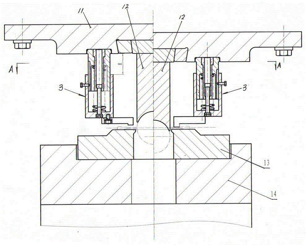
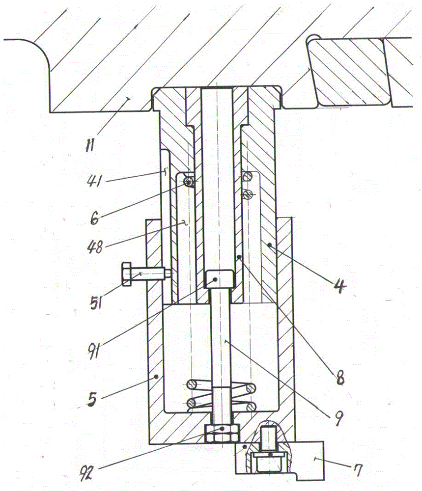
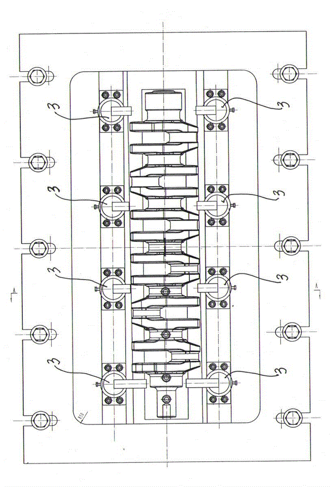
[0018] The edge trimming mold device of the present invention comprises an upper template 11, an upper punch 12, a lower die 13, a backing plate 14 under the die, and a device for unloading flash. The upper punch 12 is fixedly installed on the upper template 11, and the lower die 13 is installed on the backing plate 14 of the die, and is characterized in that a plurality of flash unloading devices 3 are distributed on the upper template 11, and the flash unloading device 3 consists of an inner sleeve 4, an outer sleeve 5, a spring 6, and a top material block 7 Composition, the upper end of the inner sleeve 4 is fixedly installed with the upper template 11, the outer sleeve 5 and the inner sleeve 4 slide and cooperate in a limited position, an anti-rotation mechanism is provided on the sliding mating surface of the outer sleeve 5 and the inner sleeve 4, and the spring 6 is installed in the inner sleeve 4 and the pressure acts on the jacket 5, and the lower end surface of the jac...


PUM


Abstract

The invention provides a die forging crankshaft and connecting-rod flash cutting die device. A plurality of flash removing devices (3) are distributed on an upper die plate (11), each of the flash removing devices (3) consists of an inner sleeve (4), an outer sleeve (5), a spring (6), an ejection block (7), a guide rod sleeve (8) and a pull rod (9), the outer sleeve (5) is matched with the inner sleeve (4) in a sliding-limiting mode, the spring (6) is installed in the inner sleeve (4) and exerts pressure on the outer sleeve (5), and the lower end face of the outer sleeve (5) is connected with the ejection block (7) through a screw. According to the size and shape of a die forging subjected to flash cutting, two or more flash removing devices (3) are distributed and installed on the upper die plate (11). The flash removing devices (3) are small in size, universal and convenient to adjust and use and is not influenced by the complication degree of die forging shapes and size change.

Description

technical field [0001] The invention relates to a die forging crankshaft and connecting rod trimming die device, in particular to the improvement of the flash unloading device for the die forging crankshaft and connecting rod trimming die device. Background technique [0002] Die forgings are divided into planes and spatial surfaces. Die forgings are of different sizes, types and complex shapes, especially for crankshafts. [0003] Die forgings are trimmed in a hot state. The upper punch and the lower die of the trimming die cooperate to trim the forging. After the upper punch enters the lower die to complete the edge trimming, the cut flash often occurs On the upper punch, so a flash unloading device is installed on the upper template of the edge trimming mold. When the upper punch resets with the upper template, the flash unloading device pushes the cut flash, and the flash is raised from the upper Remove from the mold. [0004] The flash unloading device on the edge tri...

Claims


Application Information

Patent Timeline
Patent Type & Authority Applications(China)
IPC IPC(8): B21J13/02B21J5/02
CPCB21J5/02B21J13/02B21K1/08B21K1/766
Inventor 韩晓光仇树波李海涛李贺于晓峰王泽钢
Owner LIAONING 518 INTERNAL COMBUSTION ENGINE FITTINGS
Why Eureka
Try Eureka