Machine tool for machining propeller

A propeller and processing mechanism technology, applied in metal processing equipment, milling machine equipment, manufacturing tools, etc., can solve problems such as the narrow junction between blade root and hub, low processing efficiency and precision, and affect the manufacturing accuracy of propellers, and achieve a strong position The ability to realize the posture, improve the processing efficiency, and avoid the effect of repeated positioning errors

Inactive Publication Date: 2015-03-04
JIANGSU UNIV OF SCI & TECH
View PDF6 Cites 13 Cited by
  • Summary
  • Abstract
  • Description
  • Claims
  • Application Information

AI Technical Summary

Problems solved by technology

This processing method requires multiple clamping to complete the processing of the entire propeller. The large diameter and weight of a large marine propeller make it difficult to flip and clamp, and repeated positioning errors exist in multiple clamping, which affects the manufacturing accuracy of the propeller. In addition, The roots of propeller blades are mostly curved surfaces with overlapping areas. The interference and collision problems between machine tools, tools and propellers during processing have not been completely resolved.
It also has defects, such as complex positional solution, complex NC programming, small working space, etc.
[0005] Large-scale marine propellers are typical thin-walled parts with complex curved surfaces. The junction between the blade root and the hub is relatively narrow, and the blades overlap. Most of the current propeller processing equipment is a traditional series mechanism, which is prone to flutter, interference and collision during processing. , it needs to be turned over and clamped multiple times to complete the processing of the entire propeller, and the processing efficiency and processing accuracy are low

Method used


Image

  • Machine tool for machining propeller
  • Machine tool for machining propeller
  • Machine tool for machining propeller

Examples


Embodiment Construction

[0028] The present invention will be further described below in conjunction with drawings and embodiments.

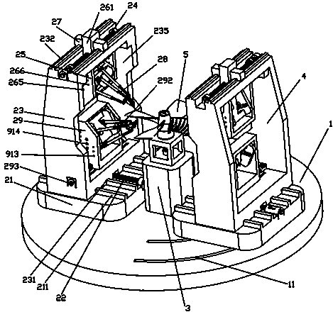
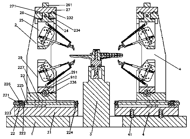
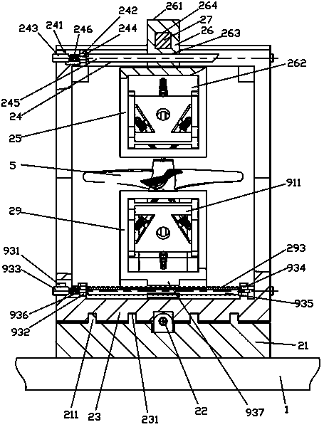
[0029] Such as figure 1 As shown, it includes a base 1, a first processing device 2, a second processing device 4 exactly the same as the first processing device 2, and a workbench 3; the workbench 3 is fixedly arranged on the center of the upper plane of the base 1, and the first The processing device 2 and the second processing device 4 are symmetrically arranged on both sides of the workbench 3 and connected to the upper plane of the base 1; the connection line between the first processing device 2 and the second processing device 4 is set in the X direction, pointing to The direction of the workbench 3 is the positive direction, and the Y direction and the Z direction can be determined according to the right-hand rule;

[0030] The first processing device 2 includes a base 21, a support guide frame 23, an upper processing mechanism 25, and a lower processing mechan...


PUM


Abstract

The invention discloses a machine tool for machining a propeller. The machine tool comprises a pedestal, a first machining device, a second machining device, and a workbench. The workbench is fixedly arranged on the pedestal, and the first machining device and the second machining device are symmetrically arranged on both sides of the workbench and are connected to the pedestal. The first machining device consists of a base, a support guide frame, an upper machining mechanism and a lower machining mechanism. The base is fixedly connected to the top surface of the pedestal, the support guide frame is fixedly arranged on the upper surface of the base, and the upper machining mechanism and the lower machining mechanism are respectively arranged on the upper part and lower part of the support guide frame. The upper machining mechanism comprises an upper fixation frame, an upper Y direction driving device, a slide carriage, and a parallel machining mechanism. The lower machining mechanism comprises a lower fixation frame, a parallel machining mechanism, and a lower Y direction driving device. According to the invention, the machine tool working space is expanded, also the rigidity and machining accuracy of the machine tool are improved, machining of the propeller can be completed by one-time clamping, and the efficiency is high.

Description

technical field [0001] The invention relates to a machine tool, in particular to a machine tool for processing propellers, and belongs to the technical field of mechanical manufacturing. Background technique [0002] So far, the processing of large marine propellers basically adopts the following schemes: 1. First, each blade and hub of the propeller are disassembled and processed independently, and then the parts are assembled for use. Due to structural limitations, the symmetry and stiffness of the propeller processed in this way are affected to a certain extent. In addition, there are cumulative errors in multiple installations, and the reliability is worse than that of the integral propeller. 2. Use a gantry-type multi-axis linkage CNC milling machine to fix the propeller on the worktable in the middle of the column. After the upper surface is processed, turn it over and then process the other side, and finally use a small amount of manual trimming. This processing meth...

Claims


Application Information

Patent Timeline
Patent Type & Authority Applications(China)
IPC IPC(8): B23C3/18
CPCB23C3/18
Inventor 方喜峰张思崇许钦桓汪通悦彭世警许风明
Owner JIANGSU UNIV OF SCI & TECH
Why Eureka
Try Eureka