Welding method of column socket of hydraulic support base

A technology of hydraulic support and welding method, which is applied in welding equipment, arc welding equipment, edge parts of workpieces, etc., can solve the problems of weak plug weld bearing capacity, large welding stress, and large plug weld welding volume, etc., so as to improve the bearing capacity. capacity and fatigue resistance, reduction in the probability of welding defects, improved safety and longevity

Inactive Publication Date: 2016-05-25
郑煤机集团潞安新疆机械有限公司
View PDF4 Cites 0 Cited by
  • Summary
  • Abstract
  • Description
  • Claims
  • Application Information

AI Technical Summary

Problems solved by technology

like figure 1 As shown, the welding method of the base column socket of the existing hydraulic support is: the bottom plate 2.1, the main rib 1.1, and the backing plate 3.1 are assembled and welded together, which makes it necessary to reserve a gap of 10 mm between the backing plate 3.1 and the inner sides of the main ribs 1.1 on both sides. ; Therefore, the width of the backing plate 3.1 is smaller than the width of the column socket 4.1; during tailor welding, there is a fillet weld 6.1 between the outer side of the main rib 1.1 and the bottom plate 2.1; 1. A plug weld is formed between the bottom plates 2.1, the fillet weld is filled after the welding fills the groove, and finally the column socket 4.1 is assembled for welding
Although the assembly welding efficiency of this welding method is high, the welding volume of the plug weld is large, and the welding process is not easy to control, which can easily cause welding defects such as virtual welding, pores, and slag inclusions, resulting in wide welding heat-affected area, large welding stress, and stress concentration.
Moreover, compared with butt welds and fillet welds, plug welds have weak bearing capacity, small penetration depth, and low fatigue resistance.

Method used


Image

  • Welding method of column socket of hydraulic support base
  • Welding method of column socket of hydraulic support base
  • Welding method of column socket of hydraulic support base

Examples


Embodiment Construction

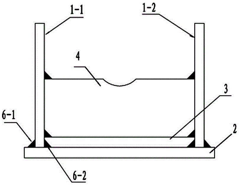
[0013] Such as figure 2 , 3 As shown, the welding method of the column socket of the hydraulic support base of the present invention is carried out according to the following steps:

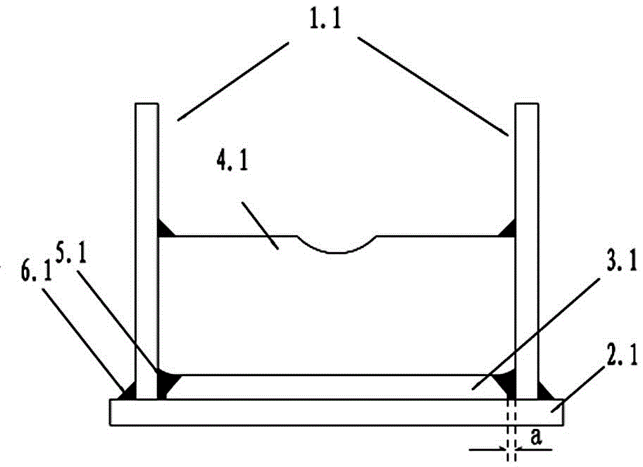
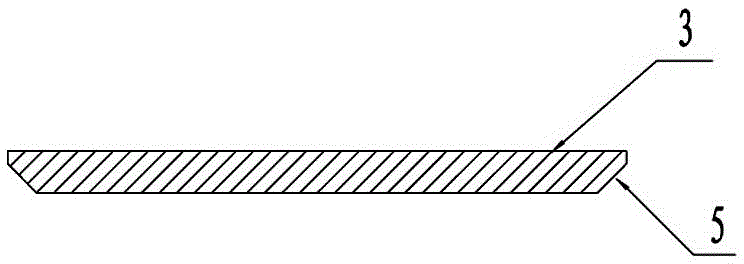
[0014] The first step is to prepare the left and right main ribs 1-1 and 1-2 according to the size of the design drawing, the bottom plate 2, the backing plate 3, and the column socket 4. The width of the backing plate 3 is equal to the width of the column socket 4, and the backing plate 3 corresponds to the The two sides of the left and right main ribs 1-1 and 1-2 are respectively provided with grooves 5 of 20mm×45°;

[0015] The second step is to use carbon dioxide gas shielded welding to tailor weld the 18mm fillet welds 6-1 and 6-2 connecting the two main ribs 1-1 and 1-2 with the bottom plate 2, and then place the 20mm×45° groove 5 of the backing plate 3 Assemble the backing plate 3 toward the bottom plate 2. When assembling the backing plate 3, avoid the 18mm fillet weld 6-2 between the ...


PUM


Abstract

The invention discloses a welding method for a hydraulic support base needling. The welding method comprises the following steps: firstly preparing a left main rib, a right main rib, a bottom plate, a cushion plate and a needling according to drawing size, wherein the width of the cushion plate is equal to the width of the needling, and respectively machining Amm*45-degree grooves in two sides, corresponding to the left main rib and the right main rib, of the cushion plate; splicing the two main ribs and the bottom plate, well welding (A-2)mm fillet welds formed when the two main ribs and the bottom plate are connected, splicing the cushion plate by enabling the Amm*45-degree grooves of the cushion plate to face to the bottom plate, and then welding fillet welds of the cushion plate and the two main ribs according to the drawing requirements, wherein the (A-2)mm fillet welds formed when the main ribs are connected with the bottom plate need to be yielded when the cushion plate is spliced; splicing the needling and then carrying out welding, wherein the weld size accords with the drawing requirements. According to the welding method of the hydraulic support base needling disclosed by the invention, plug welds at the lower part of an existing base needling are changed into the fillet welds, so that the welding defect probability is greatly reduced and the welding quality is high. The base needling welded by the welding method disclosed by the invention is firm in structure, high in bearing capability and good in rigidity.

Description

technical field [0001] The invention relates to a welding structure of a column socket of a hydraulic support base, in particular to a welding method for a column socket of a hydraulic support base. Background technique [0002] Hydraulic supports are widely used in coal mine fully mechanized mining working faces, and the column socket structure of the base of the hydraulic support is an important load-bearing component, which is continuously loaded and unloaded during the working cycle of the hydraulic support. During the use of the existing column socket structure of the hydraulic support base, phenomena such as column socket crushing and weld cracking often occur, resulting in poor load resistance and fatigue resistance. The reason is mainly due to the welded structure of the base of the hydraulic support base. Such as figure 1 As shown, the welding method of the base column socket of the existing hydraulic support is: the bottom plate 2.1, the main rib 1.1, and the bac...

Claims


Application Information

Patent Timeline
Patent Type & Authority Patents(China)
IPC IPC(8): B23K9/16B23K9/00B23K33/00
CPCB23K9/00B23K9/16B23K33/00
Inventor 高有进孟贺超冯占淼辛小超李争谷建军
Owner 郑煤机集团潞安新疆机械有限公司
Why Eureka
Try Eureka