Al technical title is built by PatSnap Al team. It summarizes the technical point description of the patent document.
A detection device and knife surface technology, applied in the direction of measuring/indicating equipment, metal processing machinery parts, metal processing equipment, etc., to achieve the effect of convenient use and accurate measurement method
Inactive Publication Date: 2015-03-04
ZHEJIANG OCEAN UNIV
View PDF10 Cites 16 Cited by
Summary
Abstract
Description
Claims
Application Information
AI Technical Summary
This helps you quickly interpret patents by identifying the three key elements:
Problems solved by technology
Method used
Benefits of technology
Problems solved by technology
[0005] Aiming at the problem that the current tool testing instruments need to manually hold the microscope camera or microscope, the present invention proposes a new tool surface wear testing method and its device
Method used
Image
Click on the blue label to locate the original text in one second.
Reading with bidirectional positioning of images and text.
Examples
Embodiment Construction
[0019] Further illustrate the present invention below in conjunction with accompanying drawing.
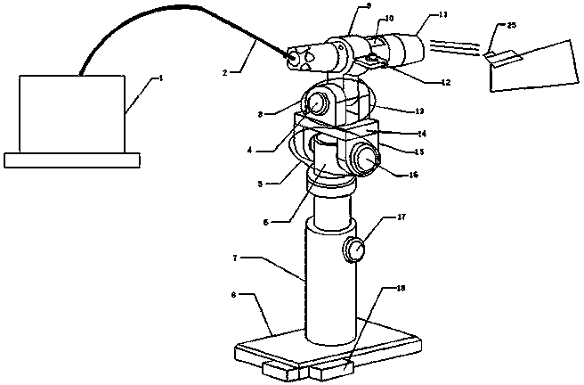
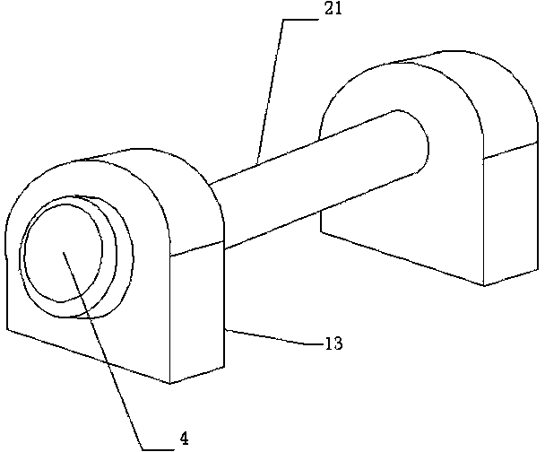
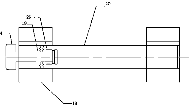
[0020] A knife surface wear detection device, including a computer 1, a USB connection line 2, a first lockable device 3, a first lockable button 4, a second lockable device 5, an inner rod 6, an outer cylinder 7, and a base 8. Microscope camera fixing ring 9, focusing knob 10, microscope camera 11, bolt 12, first support block 13, horizontal support platform 14, second support block 15, second lockable button 16, vertical knob 17, Positioning block 18, the first outer toothed disc 19, the first inner toothed disc 20, the first connecting rod 21, the second connecting rod 22, the second inner toothed disc 23, the second outer toothed disc 24 and the scale plate 25, the Described USB connection line 2 is installed on the rear end of microscope camera 11, and USB connection line 2 is connected to computer 1, and microscope camera 11 is installed in the microscope camera fixing ring ...
PUM
Abstract
The invention discloses a knife face abrasion detecting device, and belongs to the technical field of detecting equipment. The device comprises a computer, a USB connecting wire, a first locking device, a first locking button, a second locking device, an inner rod, an outer cylinder, a base, a microscope camera fixed ring, a focusing knob, a microscope camera, a bolt, a first support block, a horizontal support table, a second support block, a second locking button, a vertical knob, a positioning cushion block, a first outer fluted disc, a first inner fluted disc, a first connecting rod, a second connecting rod, a second inner fluted disc, a second outer fluted disc and a ruler piece, wherein the USB connecting wire is mounted at the back end of the microscope camera, and is connected with the computer. The device has the advantages of convenience for use, accurate measuring method, capability of detecting a cutter abrasion condition on time and guarantee smooth production.
Description
technical field [0001] The invention relates to a method and a device for detecting wear of a blade face, belonging to the technical field of detection equipment. Background technique [0002] With the continuous development of automobiles, aerospace, energy, medicine, new materials, and new technologies, cutting tools are developing towards compound, specialized, high-speed, high-precision, and diversified varieties. In addition to the improvement of tool technology, regular detection of tool wear is indispensable. Users pay more attention to efficiency improvement and optimization of input-output ratio, rather than pure price factors. [0003] After the tool is worn, the machining accuracy of the workpiece is reduced, the surface roughness is increased, and the cutting force is increased, the cutting temperature is increased, and even vibration is generated, and normal cutting cannot continue. Therefore, tool wear directly affects machining efficiency, quality and cost. ...
Claims
Application Information
Patent Timeline
Application Date:The date an application was filed.
Publication Date:The date a patent or application was officially published.
First Publication Date:The earliest publication date of a patent with the same application number.
Issue Date:Publication date of the patent grant document.
PCT Entry Date:The Entry date of PCT National Phase.
Estimated Expiry Date:The statutory expiry date of a patent right according to the Patent Law, and it is the longest term of protection that the patent right can achieve without the termination of the patent right due to other reasons(Term extension factor has been taken into account ).
Invalid Date:Actual expiry date is based on effective date or publication date of legal transaction data of invalid patent.