Pneumatic rubber expansion core shaft

A technology of rubber expansion and mandrel, which is applied in the direction of expanding mandrel, workpiece clamping device, manufacturing tool, etc., can solve the problems of high requirements on the inner wall roughness of the pipe fittings, the support and positioning of the pipe fittings cannot be accurately positioned with the center of the pipe fittings, etc. Material saving effect

Active Publication Date: 2015-03-04
CHONGQING RUIPU CABLE
View PDF6 Cites 5 Cited by
  • Summary
  • Abstract
  • Description
  • Claims
  • Application Information

AI Technical Summary

Problems solved by technology

[0003] The technical problem to be solved by the present invention is to provide a method that can accurately locate the center of the pipe

Method used


Image

  • Pneumatic rubber expansion core shaft
  • Pneumatic rubber expansion core shaft

Examples


Example Embodiment

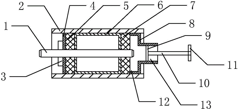
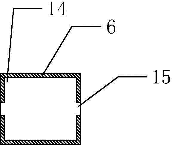
[0014] Among them: mandrel 1, pipe fitting 2, shaft shoulder 3, stopper 4, first rubber sleeve 5, top sleeve 6, second rubber sleeve 7, pneumatic cylinder 8, pneumatic valve 9, push rod 10, handle 11, large hole 12. Small hole 13, large diameter hole 14, small diameter hole 15.

[0015] Such as figure 1 As shown, the pneumatic rubber expansion mandrel 1 of the present invention includes a mandrel 1 and a top sleeve 6. The mandrel 1 is provided with a shoulder 3; the top sleeve 6 is made of duralumin, and the outer diameter of the top sleeve 6 is smaller than The inner diameter of the pipe fitting 2 is provided with a first stepped hole in the top sleeve 6. The first stepped hole includes a large-diameter hole 14 and two small-diameter holes 15 with equal radii. The large-diameter holes 14 are located in the two small-diameter holes 15 Between, such as figure 2 As shown, the top sleeve 6 is sleeved on the mandrel 1, and the two small diameter holes 15 are in clearance fit with t...


PUM


Abstract

The invention discloses a pneumatic rubber expansion core shaft. The pneumatic rubber expansion core shaft comprises a core shaft and a top sleeve, wherein the core shaft is provided with a shaft shoulder; a first stepped hole is formed in the top sleeve, the first stepped hole comprises a large-diameter hole and two small-diameter holes which are equal in radius, and the two small-diameter holes are matched with the core shaft; a first rubber sleeve and a second rubber sleeve are respectively arranged in positions, which are positioned at two sides of the top sleeve, of the core shaft in a sleeving way, the first rubber sleeve is close to the shaft shoulder, the second rubber sleeve is far away from the shaft shoulder, a separating piece is arranged between the first rubber sleeve and the shaft shoulder, the outer side of the second rubber sleeve is also provided with a pneumatic cylinder, the pneumatic cylinder is also internally provided with a pneumatic valve, the pneumatic valve leans against the inner wall of the pneumatic cylinder, and the outer side of the pneumatic valve is provided with a pushing rod. According to the pneumatic rubber expansion core shaft disclosed by the invention, the technical defect that the supporting location on a pipe cannot be accurately carried out by using the pipe as the center or the requirement on the roughness of the inner wall of the pipe is higher at present is overcome, accurate location can be carried out by using the pipe as the center, and the requirement on the roughness of the inner wall of the pipe is not high.

Description

technical field [0001] The invention belongs to the field of support and positioning of pipe fittings, and in particular relates to a pneumatic rubber expansion mandrel. Background technique [0002] At present, when processing pipe fittings, jaws are usually used to clamp the end of the pipe fittings, and then the rotation of the gripper jaws is used to drive the rotation of the pipe fittings, thereby processing the outer wall of the pipe fittings. At that time, the pipe fittings were not positioned by the center of the inner hole of the pipe fittings. Therefore, the machining accuracy of the pipe fittings cannot be guaranteed when the pipe fittings are finished. In actual operation, some people use the mandrel to position the pipe fittings, that is, the pipe fittings Put it on the mandrel, and then drive the pipe to rotate through the rotation of the mandrel, so as to process the pipe. It is located in the center of the pipe fittings, so the roughness of the inner wall of...

Claims


Application Information

Patent Timeline
IPC IPC(8): B25B11/00
CPCB23B31/4053
Inventor 王云
Owner CHONGQING RUIPU CABLE
Why Eureka
Try Eureka