Continuously variable speed bicycle with friction wheel transmission
What is Al technical title?
Al technical title is built by PatSnap Al team. It summarizes the technical point description of the patent document.
A friction wheel drive, continuously variable speed technology, applied in wheel transmission, vehicle gearbox, vehicle components and other directions, can solve the problems of high cost, limited speed change range, complex stepless speed change structure, etc., to achieve low cost, speed change The effect of large amplitude and stepless speed regulation is simple and convenient
Inactive Publication Date: 2016-06-22
ZHEJIANG UNIVERSITY OF SCIENCE AND TECHNOLOGY
View PDF5 Cites 0 Cited by
Summary
Abstract
Description
Claims
Application Information
AI Technical Summary
This helps you quickly interpret patents by identifying the three key elements:
Problems solved by technology
Method used
Benefits of technology
Problems solved by technology
[0005] In order to solve the problems of limited range of speed change in stepped speed change of bicycles, complicated structure and high cost of stepless speed change in the past, the present invention provides a method that can realize stable speed change under any road conditions, with large speed change range and stable speed change; at the same time, it can By modifying the existing bicycles, the continuously variable speed bicycles driven by friction wheels are simple to manufacture, low in cost, reasonable in economy and strong in applicability
Method used
Image
Click on the blue label to locate the original text in one second.
Reading with bidirectional positioning of images and text.
Examples
Embodiment Construction
[0036] The present invention will be described in further detail below in conjunction with the accompanying drawings and specific principles of use, but it is not intended to limit the protection scope of the present invention.
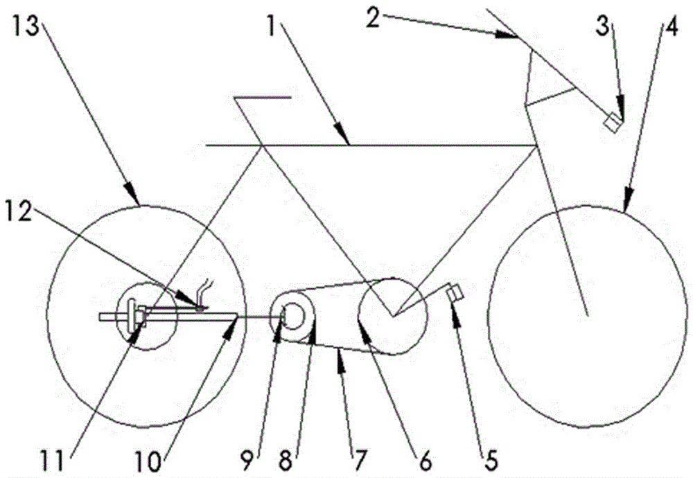
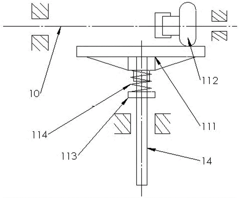
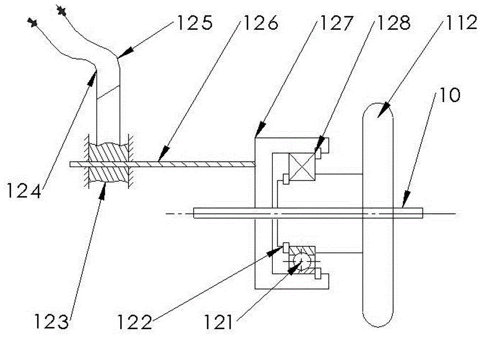
[0037] The continuously variable speed bicycle of the friction wheel transmission of the present invention comprises figure 1 Vehicle frame 1, handle 2, speed control handle 3, front wheel 4, pedal 5, front flywheel 6, chain 7, rear flywheel 8, rotating shaft 10, rear wheel 13 in the figure 2 Friction disc 111, friction wheel 112, adjustment nut 113, spring 114, deep groove ball bearing, rear axle 14 in the image 3 Among 121, snap ring (1) 122, winding nut 123, the first bidirectional steel wire rope 124, the second bidirectional steel wire rope 125, speed regulating screw 126, card wheel 127, snap ring (2) 128, Figure 4 The first bevel gear 91, the second bevel gear 92,
[0038] Rear flywheel 8 is installed on the rear fork of vehicle frame 1, a...
PUM
Abstract
The invention discloses a friction wheel transmission stepless transmission bicycle, which comprises a bicycle frame, handlebars, a speed regulating handle, a front wheel, pedals, a front flywheel, a chain, a back flywheel, a rotating direction changing device, a rotating shaft, a friction wheel transmission device, a speed regulating device, a back wheel and a back wheel axle, wherein the rotating direction changing device comprises two mutually engaged bevel gears, one bevel gear is synchronously connected with the back fly wheel, the other bevel gear is connected with the rotating shaft, further, the rotating input of the rotating shaft is realized, the friction wheel transmission device comprises a friction disc, a spring, a regulating screw nut and a friction wheel, the friction disc, the spring and the regulating screw nut are arranged on a back axle, the friction wheel synchronously rotates with the rotating shaft, one end of the rotating shaft is provided with a spline, a friction wheel is glidingly connected onto the spline position, and the friction wheel is in vertical and tight contact with the friction disc. The friction wheel transmission stepless transmission bicycle has the advantages that the stable speed change can be realized under any road conditions, the speed change amplitude is great, the speed change is stable, meanwhile, through the modification on the existing bicycle, the manufacturing is simple, the cost is low, economic performance and reasonableness are realized, and the applicability is high.
Description
technical field [0001] The invention relates to a vehicle, in particular to a continuously variable speed bicycle driven by friction wheels. Background technique [0002] Bicycles have been invented and used for more than 550 years. According to the needs of different users, bicycles can be divided into single-stage, multi-stage and continuously variable speed bicycles. The continuously variable speed bicycles currently on the market mainly refer to TheRide New Finch CVT star transmission bicycle invented in 1999. This product is to install a transmission box at the rear axle of the bicycle, and place two thin metal discs inside as power. The input and output device boldly cancels the chain gear shift setting of the previous bicycle, and the shift device completely relies on the fuzzy adjustment device integrated with the handlebar of the bicycle. By adjusting the arc of a group of small balls in the CVP continuously variable transmission box contacting the power input turnt...
Claims
Application Information
Patent Timeline
Application Date:The date an application was filed.
Publication Date:The date a patent or application was officially published.
First Publication Date:The earliest publication date of a patent with the same application number.
Issue Date:Publication date of the patent grant document.
PCT Entry Date:The Entry date of PCT National Phase.
Estimated Expiry Date:The statutory expiry date of a patent right according to the Patent Law, and it is the longest term of protection that the patent right can achieve without the termination of the patent right due to other reasons(Term extension factor has been taken into account ).
Invalid Date:Actual expiry date is based on effective date or publication date of legal transaction data of invalid patent.
Patent Type & Authority Patents(China)
IPC IPC(8): B62M11/10B62M11/12
CPCB62M11/10B62M11/12
Inventor 陈岁繁段福斌宋德玉李其朋莫文林叶正挺周禅
Owner ZHEJIANG UNIVERSITY OF SCIENCE AND TECHNOLOGY