Welding manipulator driving device

A technology for welding manipulators and driving devices, applied in fluid pressure actuating devices, auxiliary devices, mechanical equipment, etc., can solve the problems of unstable output, large compressed air compression ratio, unstable cylinder output, etc., to prevent leakage, accurate Control and solve the effect of unstable output

Inactive Publication Date: 2015-03-04
CHONGQING XIHUA BELT PULLEY MACHINERY MFG CO LTD
View PDF0 Cites 1 Cited by
  • Summary
  • Abstract
  • Description
  • Claims
  • Application Information

AI Technical Summary

Problems solved by technology

[0005] The beneficial effects of this scheme are: use a part of the piston chamber of the cylinder as an oil chamber, and feed hydraulic oil through the hydraulic oil inlet and outlet, and the hydraulic oil inlet and outlet are connected to the oil tank provided outside the cylinder through the oil inlet pipeline, and the oil tank There is an air chamber inside, and the problem of high compression ratio and unstable output of compressed air is solved by injecting hydraulic oil into the cylinder. On the other hand, the oil tank is located outside the cylinder and is not installed on the welding manipulator, which will not affect the operation of the welding manipulator. Flexibility, the welding manipulator only needs to install the cylinder. In addition, the structure of the present invention is simple, and only needs to configure an oil tank on the original cylinder. The cost is much lower than that of the existing gas-liquid damping cylinder, but it can also solve the problem. The problem of unstable cylinder output

Method used


Image

  • Welding manipulator driving device

Examples


Embodiment Construction

[0010] The present invention will be described in further detail below by means of specific embodiments:

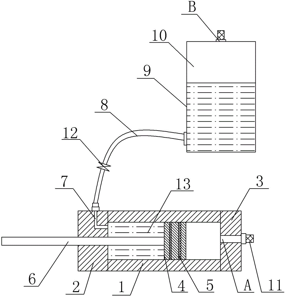
[0011] The reference signs in the accompanying drawings of the specification include: 1- cylinder body; 2- front cover; 3- rear cover; 4- piston; 5- piston sealing ring; 6- piston rod; 7- hydraulic oil inlet and outlet; 8- inlet Oil pipeline; 9-oil tank; 10-air chamber; 11-cylinder muffler; 12-needle valve; 13-oil chamber.

[0012] The embodiment is basically as attached figure 1 Shown: The driving device of the welding manipulator, including a single-acting cylinder, including cylinder block 1, front cover 2 and rear cover 3 from left to right. A piston cavity is opened in the cylinder body 1, a piston 4 is installed in the piston cavity, and at least two piston sealing rings 5 ​​are fixed on the side wall of the piston 4. The piston 4 is connected with a piston rod 6 extending through the front cover 2 . The front cover 2 has a hydraulic oil inlet and outlet 7 commun...


PUM


Abstract

The invention relates to a welding manipulator driving device, which belongs to the technical field of fluid braking devices. The welding manipulator driving device comprises an air cylinder, wherein the air cylinder is divided into a front cover, a cylinder body and a back cover, a piston cavity is formed in the cylinder body, a piston is installed in the piston cavity, a piston rod which is connected with the piston penetrates through the front cover, and a first air port is formed in the back cover. The welding manipulator driving device is characterized in that a hydraulic oil port which is communicated with the piston cavity is formed in the front cover, the hydraulic oil port is connected with the bottom of an oil tank outside the air cylinder through an oil inlet pipeline, and a speed regulating valve is installed on the oil inlet pipeline; hydraulic oil is contained in the oil tank, an air chamber is left in the upper part of the oil tank, and a second air port which is communicated with the air chamber is formed in the top of the oil tank. The welding manipulator driving device has the advantage of simple structure, only one oil tank needs to be arranged on the original air cylinder, and compared with an existing gas-liquid damping type air cylinder, the air cylinder is lower in the cost, but the problem of unstable output of the air cylinder can be solved.

Description

technical field [0001] The invention belongs to the technical field of fluid braking devices. Background technique [0002] In motorcycle, or auto parts processing factories or other mechanical processing factories, welding manipulators are commonly used to weld parts. The welding manipulator is mainly driven and controlled by cylinders. Conventional cylinders include cylinders, piston rods and piston rods. The connected manipulator implements the structure, and two air inlets and outlets are arranged on the cylinder body for introducing air. The disadvantage of this kind of cylinder is: the cylinder uses compressed air as the power source. Due to the large compression ratio of the air, the output stability of the cylinder is poor, and there may be situations where the welding manipulator stops or the speed changes suddenly when moving. In order to solve the above problems, Now there is a hydraulic damping cylinder on the market, which adopts the oil cylinder and the cylind...

Claims


Application Information

Patent Timeline
Patent Type & Authority Applications(China)
IPC IPC(8): F15B11/00F15B15/14B23K37/00
CPCF15B15/1428B23K37/00F15B15/20
Inventor 唐建瑶
Owner CHONGQING XIHUA BELT PULLEY MACHINERY MFG CO LTD
Why Eureka
Try Eureka